Sliding contact arrangement with wear elimination

A sliding contact, component technology for applications in the field of systems with particles and abrasive substances

Active Publication Date: 2009-10-07
SCHLEIFRING & APPBAU
View PDF1 Cites 10 Cited by
  • Summary
  • Abstract
  • Description
  • Claims
  • Application Information

AI Technical Summary

Problems solved by technology

It has been found that this configuration, especially with regard to newer computerized tomographs with a larger current

Method used


Image

  • Sliding contact arrangement with wear elimination
  • Sliding contact arrangement with wear elimination
  • Sliding contact arrangement with wear elimination

Examples


Embodiment Construction

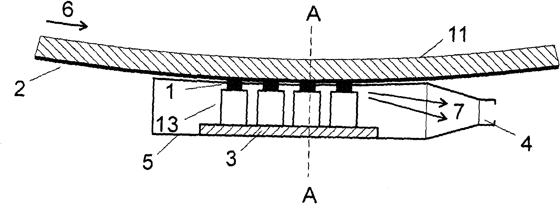
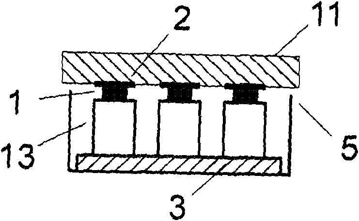
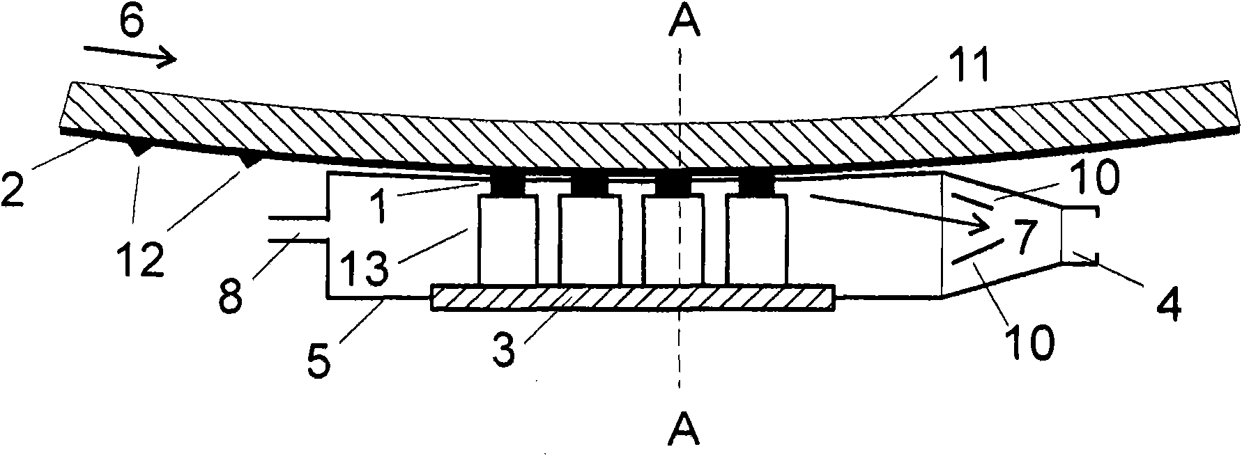
[0020] figure 1 A partial view showing the device of the present invention. Here, for example, four brushes are provided, each of which is accommodated in the stem 13 . The sliding contact assembly includes at least one brush. However, depending on the current to be carried, the sliding contact assembly may also comprise a large number of brushes, eg 20 brushes. If several current paths or also signal paths are provided at the same time, a suitable number of brushes is provided individually for each path and runs along the relevant rails. A typical sliding contact assembly for a computerized tomograph may include 50 or more brushes. The brushes are grouped together in the brush block 3 . The brush blocks generally accommodate the sockets of the brushes and make contact with these sockets. There is a special construction in which multiple brush blocks are also provided. Such a configuration may be necessary, for example, to increase insulation. The brushes are in sliding...


PUM


Abstract

A sliding contact arrangement comprises at least one slideway and, running thereon, at least one brush. Furthermore, a collecting vessel is provided through which the air flow caused by the movement of the slideway with respect to the brush flows. At the end of the cover, a collecting vessel for accommodating the particles transported by the air flow is provided. The collecting vessel can have a filter or else additional means for producing turbulence with the result that the air flow discharges the particles in the filter.

Description

technical field [0001] The present invention relates to a sliding contact assembly and, in particular, to a system for removing particles and abrasive matter formed by sliding contact movement along a contact rail. Sliding contact assemblies are used for electrical connections and, in particular, for transmitting signals between two units that are movable relative to each other. Here, the brushes are in electrical contact with the slide rail and are movable relative thereto. Basically, the brushes can move linearly or rotationally depending on the configuration of the rail. The term brush element or brush is used herein to mean any brush, wire, or pin contact, which may be made of metal, conductive plastic material, carbonaceous material, and other materials known in the art . It is necessary that the contacts have at least a minimum electrical conductivity. Slide rails are usually constructed of metal such as brass or stainless steel. However, the slide rail can also be ...

Claims


Application Information

Patent Timeline
IPC IPC(8): H01R39/38
CPCH01R39/48H02K9/28
Inventor H·席林
Owner SCHLEIFRING & APPBAU
Why Eureka
Try Eureka