
Fruit plucker
A picker and fruit technology, applied in the field of pickers with a clamping mechanism and a shearing mechanism, can solve the problems of large picking head, increase the complexity of the structure, increase energy consumption, etc., and achieve simple operation and control, adaptability Strong, easy-to-handle effects
- Summary
- Abstract
- Description
- Claims
- Application Information
AI Technical Summary
Problems solved by technology
Method used
Image

Examples
Embodiment Construction
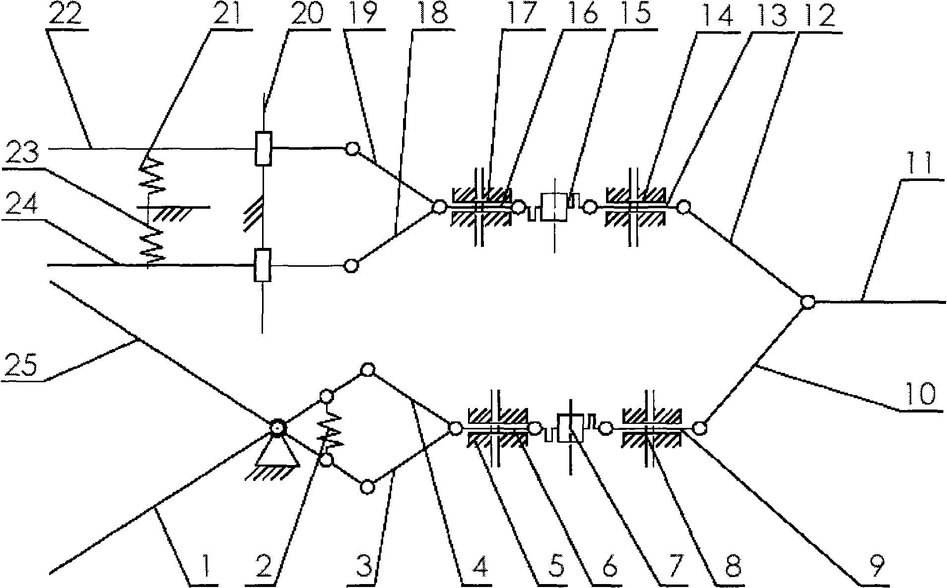
[0016] The invention provides a fruit picker, such as figure 1 As shown, it includes a pull rod, a flexible shaft assembly, a reset device, a sliding mechanism, a clamp handle and a shear handle. One end of the first pull rod 11 is connected to the drive mechanism, and the other end is connected to one end of the second and third pull rods 10 and 12 respectively. The other end of the second pull rod 10 is hinged with one end of the first flexible shaft assembly, the other end of the first flexible shaft assembly is respectively hinged with one end of the fourth and fifth pull rods 3,4, and the fourth and fifth pull rods The other ends of 3 and 4 are respectively hinged to the two shear handles 1 and 25, the other end of the third pull rod 12 is hinged to one end of the second flexible shaft assembly, and the other end of the second flexible shaft assembly is respectively connected to the sixth and seventh One end of pull rod 18,19 is hinged, and the other end of the 6th, the 7...
PUM
 Abstract
Description
Claims
Application Information