Caliper brake device for vehicle

A brake device and caliper-type technology, which is applied in the direction of brake types, railway brake systems, axial brakes, etc., can solve the problems of inability to reduce the friction coefficient of brake pads, uneven wear of brake pads, temperature rise, etc. question

Inactive Publication Date: 2009-10-28
KYB CORP
View PDF5 Cites 18 Cited by
  • Summary
  • Abstract
  • Description
  • Claims
  • Application Information

AI Technical Summary

Problems solved by technology

As a result, the caliper sometimes bends due to the reaction force against the pressing, and reliable contact with the friction surface cannot be ensured
In addition, the brake pads may not be able to exert their original braking force due to a local temperature rise in the brake pads and a decrease in the friction coefficient of the brake pads.
As a result, brake pads are also prone to uneven wear
[0007] In particular, in the case of an air brake using a lever, it is difficult to press the brake pad evenly against the friction surface due to the influence of the frictional force acting on the bearing portion of the lever, and the brake pad is prone to malfunction. Uniform wear

Method used


Image

  • Caliper brake device for vehicle
  • Caliper brake device for vehicle
  • Caliper brake device for vehicle

Examples


Embodiment Construction

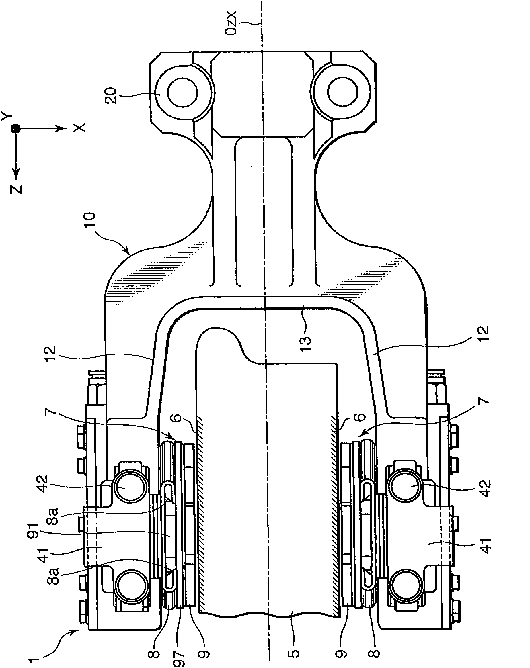
[0021] refer to figure 1 A caliper brake device 1 for a railway vehicle uses a pair of brake pads 7 to brake the rotation of a wheel 5 . In the figure, the X-axis corresponds to the axial direction of the wheel 5 , the Y-axis corresponds to the vertical direction, and the Z-axis corresponds to the front-rear direction. On both side surfaces of the wheel 5 , a pair of friction surfaces 6 are formed in advance for a pair of brake pads 7 .

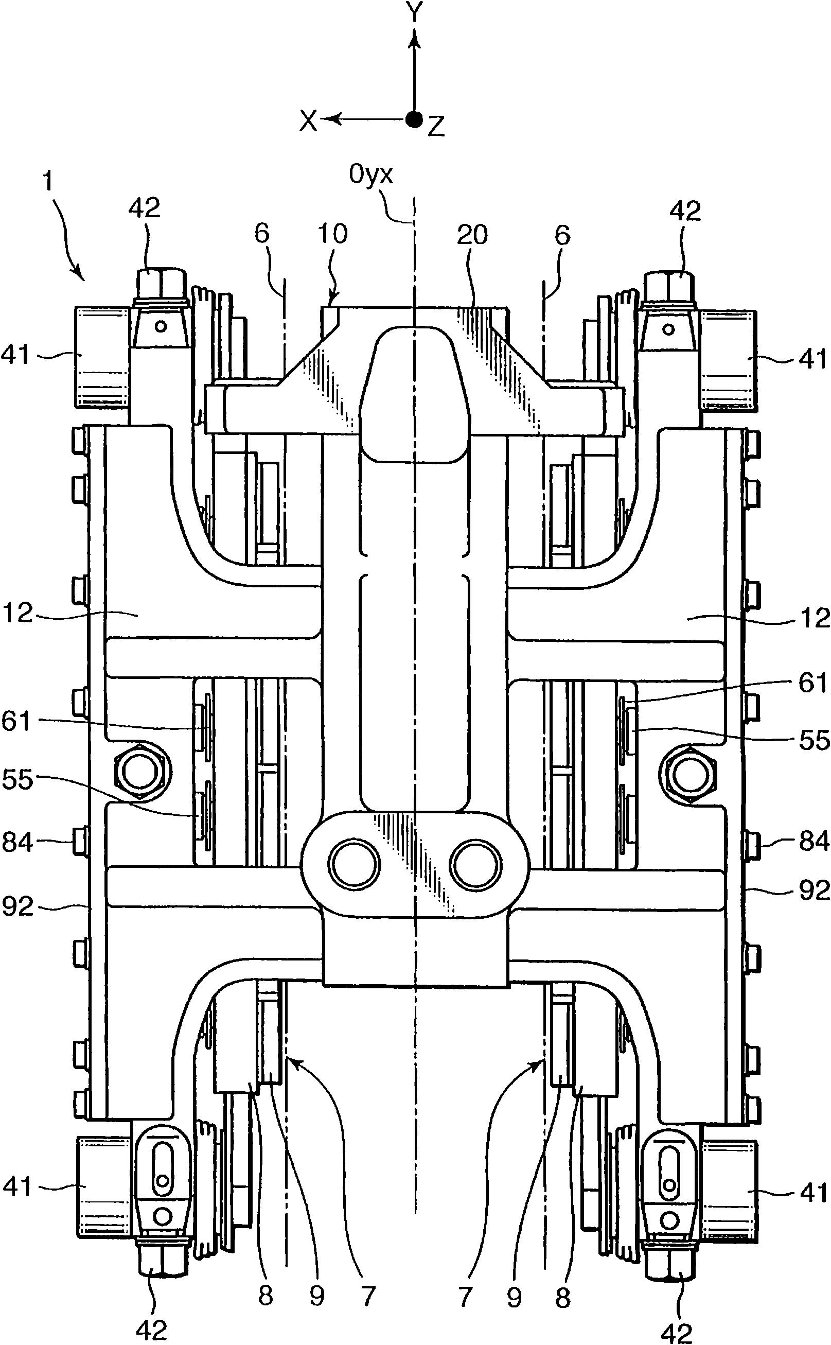
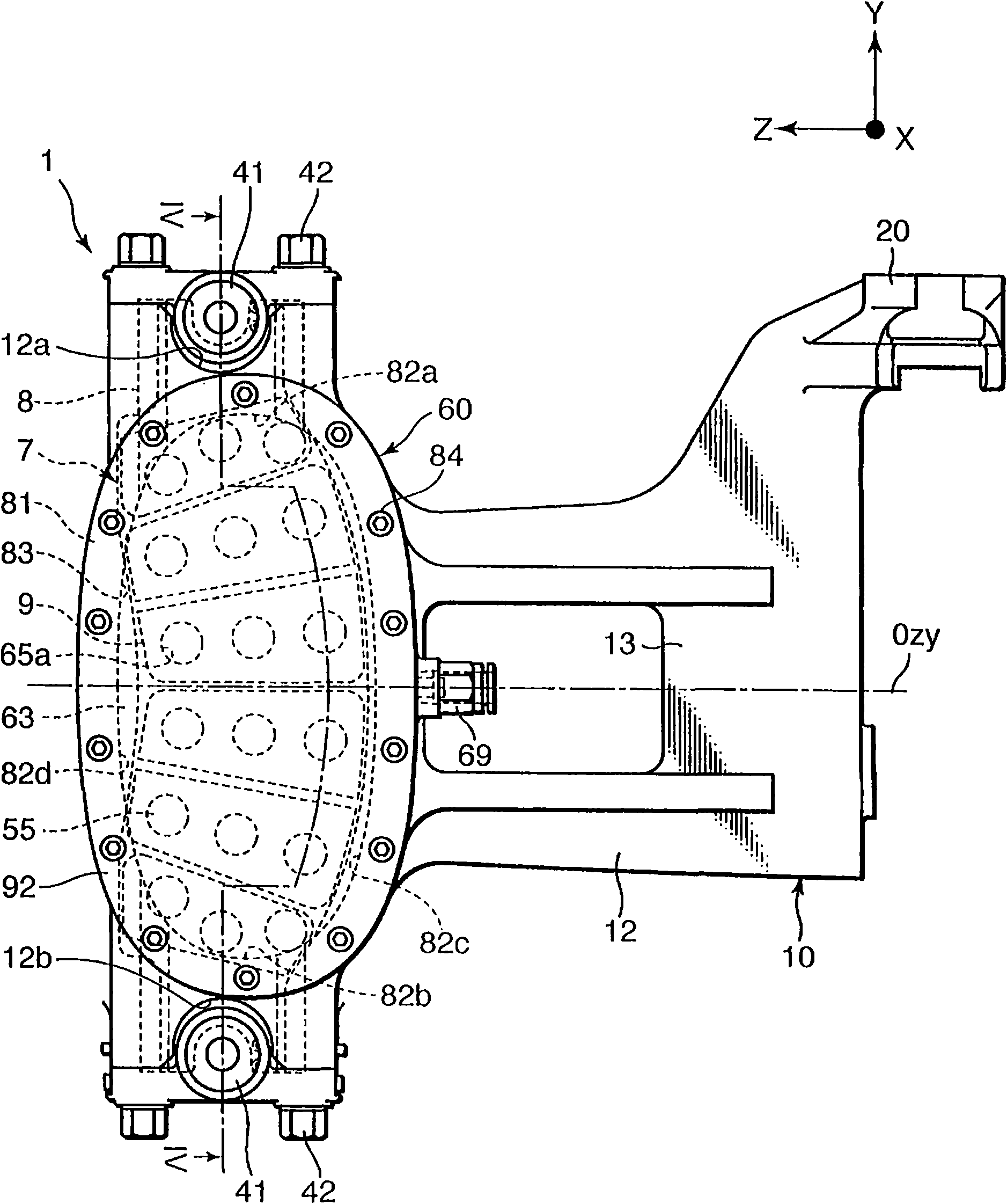
[0022] A pair of brake pads 7 are respectively supported on the front ends of a pair of caliper arms 12 . A pair of caliper arms 12 is branched into two forks from a yoke 13 of the caliper 10 across the wheel 5 . The brake caliper 10 includes a flange portion 20 . The flange part 20 is fixed to the dolly of the railway vehicle with bolts.

[0023] Brake caliper 10 has a relative figure 1 centerline O zx shown and figure 2 The centerline Oyx symmetric shape shown.

[0024] refer to image 3 and Figure 4 , in order to drive the bra...


PUM


Abstract

The invention provides a brake caliper (10) having a pair of caliper arms (12) facing friction surfaces (6) on both sides of a wheel (5). The caliper arms (12) press brake pads (7) to the friction surfaces (6) to brake the wheel (5). In a caliper arm (12) is formed a pressure chamber (63) defined by a diaphragm (75). The caliper arm (12) has pistons (55) for driving a brake pad (7) in response to inflation of the diaphragm (75) occurring when compressed air is supplied into the pressure chamber (63), and the caliper arm (12) also has a guide member (65) for guiding movement of the pistons (55) in the direction normal to the friction surface (6). The movable brake pads (7) apply a uniform braking force to the wheel (5).

Description

technical field [0001] The present invention relates to a caliper brake device for a vehicle that brakes a rotating body by sandwiching two friction surfaces formed on both side surfaces of the rotating body. Background technique [0002] Railway vehicles are generally equipped with an air-hydraulic converter that converts air pressure supplied from an air pressure source to hydraulic pressure, and hydraulic brakes are operated by the oil pressure supplied from the air-hydraulic converter through hydraulic piping. [0003] Regarding this point, Japanese Patent Application Publication No. 8-226469 and Japanese Patent Application Publication No. 8-226471 issued by the Japanese Patent Office in 1996 disclose that a hydraulic cylinder presses the brake pad against the brake rotor according to the supplied oil pressure. A hydraulic brake device for railway vehicles on the friction surface of the rotating body. [0004] On the other hand, it is generally considered to eliminate t...

Claims


Application Information

Patent Timeline
Patent Type & Authority Applications(China)
IPC IPC(8): F16D65/20B61H5/00F16D55/228F16D65/095F16D65/18
CPCF16D55/2245B61H5/00F16D2125/12F16D65/095F16D55/224F16D65/097
Inventor 铃木努若林浩明大河原义之
Owner KYB CORP
Why Eureka
Try Eureka