Co2 refrigerant system with tandem compressors, expander and economizer

A refrigerant system and refrigerant technology, applied in irreversible cycle compression machines, compressors, refrigerators, etc., to achieve the effect of improving performance

Inactive Publication Date: 2009-10-28
CARRIER CORP
View PDF0 Cites 7 Cited by
  • Summary
  • Abstract
  • Description
  • Claims
  • Application Information

AI Technical Summary

Problems solved by technology

However, to date there is no refrigerant system that includes a combined expander, tandem compressor, and economizer cycle that provides a powerful combination of operating options and enhanced features

Method used


Image

  • Co2 refrigerant system with tandem compressors, expander and economizer
  • Co2 refrigerant system with tandem compressors, expander and economizer
  • Co2 refrigerant system with tandem compressors, expander and economizer

Examples


Embodiment Construction

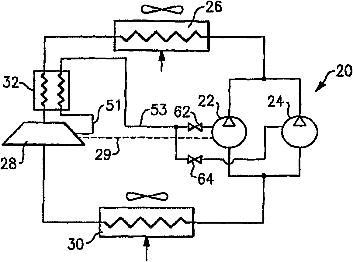
[0015] figure 1 Refrigerant system 20 is illustrated. As shown, two compressors 22 and 24 operate in tandem to provide compressed refrigerant and deliver the refrigerant throughout refrigerant system 20 . Obviously, more than two compressors can be arranged in parallel and operated simultaneously or individually according to the heat load demand in the conditioned space. Although in figure 1 In the conventional arrangement shown, the tandem compressors have a common suction header and a common discharge header, as known to those skilled in the art, but the tandem compressors could also have a common suction header. Gas headers and separate exhaust lines, as well as having separate suction lines and common exhaust headers. Additionally, tandem compressors 22 and 24 may have oil and steam balance lines (not shown), as known to those skilled in the art.

[0016] The compressed refrigerant flows through heat exchanger 26 and to expander 28 downstream. As known to those skille...


PUM


Abstract

A refrigerant system utilizes an expander that provides a more efficient expansion process and recovers at least a portion of energy from this expansion process. At least a portion of refrigerant that has been at least partially expanded in the expander is tapped and passed through an economizer heat exchanger. In the economizer heat exchanger, the tapped refrigerant cools a main circuit refrigerant increasing its thermodynamic potential. Further, a compression section is provided with at least two compressors operating in tandem and allowing for multiple stages of unloading. By selectively utilizing one or more of the tandem compressors, the economizer cycle, and the expander, the refrigerant system can achieve very efficient operation and provide enhanced control flexibility, in particular, for the CO2 refrigerant system operating in the transcritical cycle.

Description

technical field [0001] The present application relates to a refrigerant system in which an expander is used to provide a more efficient expansion process by withdrawing energy from the expansion process and utilizing the energy to power at least one system component. A portion of the refrigerant is diverted from a location within the expander where the portion of the refrigerant has been at least partially expanded, and the diverted refrigerant is then used to subcool the main refrigerant flow within the economizer heat exchanger. In this manner, a single expander can provide and augment both a primary expansion device function and an economizer expansion device function for a refrigerant system. Furthermore, the refrigerant system includes multiple tandem compressors, only some of which can be economized. Finally, the refrigerant system can be charged with CO 2 refrigerant, the system operates in a transcritical cycle at least part of the time. Background technique [00...

Claims


Application Information

Patent Timeline
Patent Type & Authority Applications(China)
IPC IPC(8): F25B1/00
CPCF25B2400/13F25B9/06F25B2600/2509F25B1/10F25B9/008F25B2309/061F25B2309/06F25B2400/075F25B2400/0751F25B2400/02
Inventor A·利夫森M·F·塔拉斯
Owner CARRIER CORP
Why Eureka
Try Eureka