Air treatment system combining trans-critical circulation and solution dehumidification system

An air treatment system and solution dehumidification technology, which is applied in air conditioning systems, space heating and ventilation, household heating, etc., can solve problems such as inability to perform dehumidification process, and achieve the effect of improving performance

Active Publication Date: 2017-01-04
ZHEJIANG UNIV
View PDF9 Cites 6 Cited by
  • Summary
  • Abstract
  • Description
  • Claims
  • Application Information

AI Technical Summary

Problems solved by technology

However, it is limited to the cooling functi...

Method used


Image

  • Air treatment system combining trans-critical circulation and solution dehumidification system
  • Air treatment system combining trans-critical circulation and solution dehumidification system
  • Air treatment system combining trans-critical circulation and solution dehumidification system

Examples


Embodiment 1

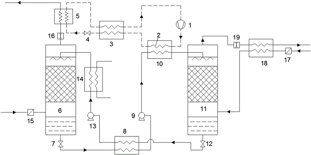
[0074] Such as figure 1 As shown, the air treatment system combined with the transcritical circulation and solution dehumidification system in this embodiment includes: a transcritical compression subsystem and a solution dehumidification subsystem, wherein the solution dehumidification subsystem includes a concentrated solution dehumidification unit and a dilute solution regeneration unit;

[0075] The concentrated solution dehumidification unit includes:

[0076] The concentrated solution flow regulating valve 12, the first heat exchange channel of the solution heat exchanger 8, the concentrated solution pump 13, the cooler 14, the dehumidifier 6, the first filter 15, the first fan 16 and the first exchange channel of the evaporator 5 Hot channel; the outlet of the concentrated solution flow regulating valve 12 is connected to the inlet of the first heat exchange channel of the solution heat exchanger 8, the outlet of the first heat exchange channel of the solution heat exch...

Embodiment 2

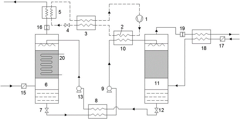
[0093] Such as figure 2 As shown, the air treatment system in this embodiment combined with transcritical circulation and solution dehumidification system has the same structure as the treatment system in Embodiment 1 except that the dehumidification process is isothermal dehumidification. in the filler of the dehumidifier 6; the cooling coil 20 takes away the heat generated during the dehumidification process in time to keep the temperature of the desiccant solution constant and improve the dehumidification capacity; at the same time, the heat exchange temperature difference of the solution heat exchanger 8 increases, and the low temperature dilute The solution can better cool the high-temperature concentrated solution, thereby reducing the input of external cold sources and saving energy.


PUM


Abstract

The invention discloses an air treatment system combining trans-critical circulation and a solution dehumidification system. The air treatment system is characterized in that the system comprises a trans-critical compression subsystem and a solution dehumidification subsystem, heat discharged by a high-pressure side of the trans-critical compression subsystem serves as a heat source of the solution dehumidification subsystem, the solution dehumidification subsystem comprises a strong solution dehumidification unit and a dilute solution regenerating unit, and a dehumidification process is a heat insulation dehumidification process. The invention further discloses an air treatment system combining trans-critical circulation and a solution dehumidification system, and a dehumidification process is a constant-temperature dehumidification process. Reasonable energy coupling of the trans-critical circulation and the solution dehumidification system is achieved, dehumidification and temperature falling of the air can be simultaneously achieved, overall performance of the dehumidification system is improved, the heat discharged by the high-pressure side of the compression subsystem basically meets regenerated heat requirements when trans-critical compression refrigeration circulation refrigerating temperature ranges from 7 DEG C to 12 DEG C and can completely meet the regenerated heat requirements when the cooling temperature of a dehumidifying agent drops, compression work can be decreased by 10% or more, and the system is simple in structure and excellent in overall economy and environmental protection.

Description

technical field [0001] The invention relates to the field of air heat and humidity treatment, in particular to an air treatment system combined with a transcritical cycle and a solution dehumidification system. Background technique [0002] As early as more than 60 years ago, Lof proposed the concept of solution dehumidification, using triethylene glycol (TEG) as a moisture absorbent, and using solar energy for regeneration. In recent years, with the prominent problem of energy shortage, solution dehumidification has become a research hotspot at home and abroad because of its characteristics of utilizing renewable energy and low-grade waste heat. [0003] For example, the Chinese patent document with application number 201610137413.3 discloses a solution dehumidification system and method driven by low-temperature waste heat, which relates to the technical fields of solution dehumidification and waste heat refrigeration. The system includes regenerator, solution pump, solut...

Claims


Application Information

Patent Timeline
IPC IPC(8): F24F5/00
CPCF24F3/1417F24F5/001F24F5/0014F24F2003/1458F24F2221/34
Inventor 何一坚王祎陈香玉李荣
Owner ZHEJIANG UNIV
Why Eureka
Try Eureka