Phased array antenna system with electrical tilt control

A phased array antenna, tilt control technology, applied in specific array feeding systems, individually powered antenna arrays, antennas, etc., can solve the problems of reducing antenna gain, complex phased array antennas, high cost and weight, etc.

Inactive Publication Date: 2009-11-11
QUINTEL TECH
View PDF10 Cites 21 Cited by
  • Summary
  • Abstract
  • Description
  • Claims
  • Application Information

AI Technical Summary

Problems solved by technology

Amplitude tapering is primarily concerned with setting antenna sidelobe levels, but has the side effect of reducing gain
Phase cone reduction is mainly related to setting the electrical tilt angle, but also reduces antenna gain and increases sidelobe levels if it is not linear
[0017] Existing techniques for electrical tilting of phased array antennas using multiple variable phase shifters or delay devices are rather complex: they result in high cost and weight and require separate antennas for each carrier frequency or for each Electrical tilt angles are unrealistic for antenna operators

Method used


Image

  • Phased array antenna system with electrical tilt control
  • Phased array antenna system with electrical tilt control
  • Phased array antenna system with electrical tilt control

Examples


Embodiment Construction

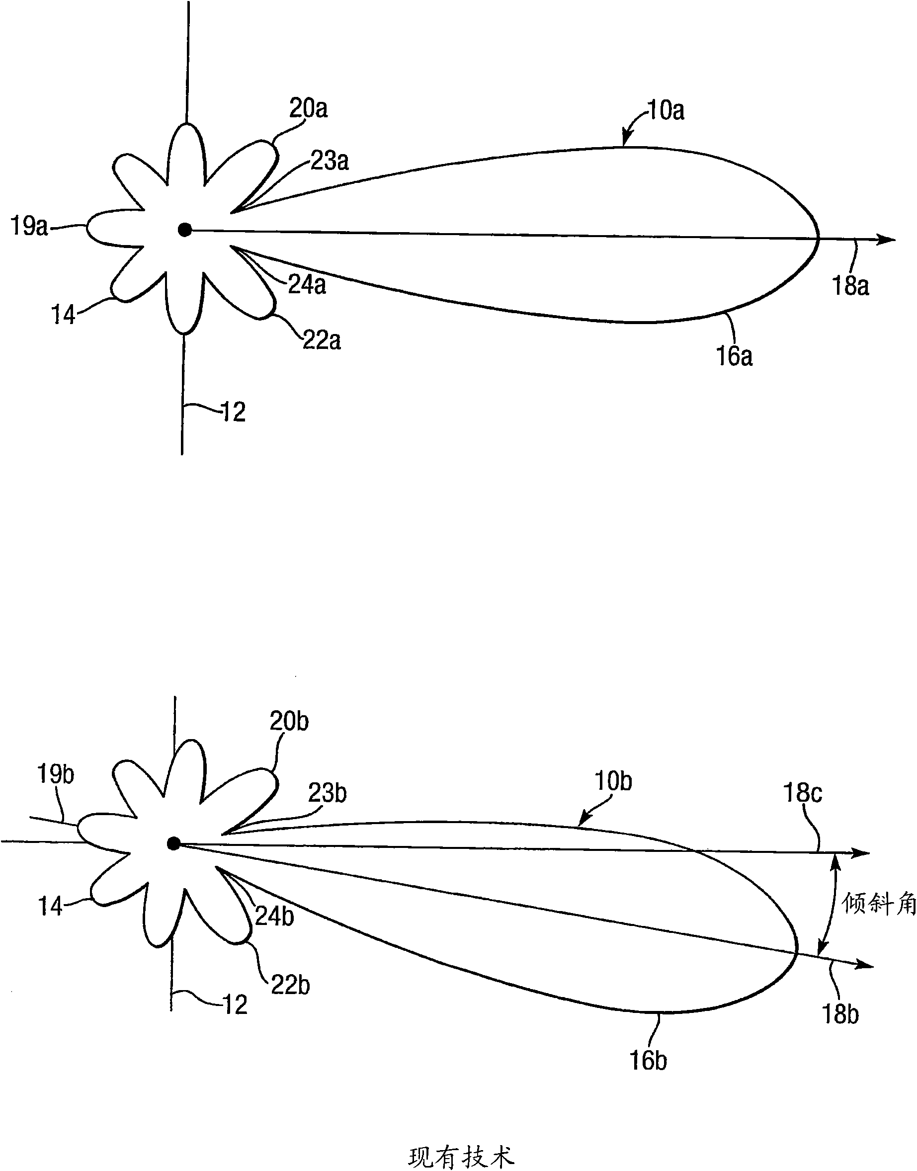
[0065] refer to figure 1 , shows vertical radiation patterns (VRP) 10a and 10b of a phased array antenna 12 consisting of an array of antenna elements (not shown). The antenna 12 is linear, has a center 14 and is arranged vertically in the plane of the drawing. VRPs 10a and 10b correspond to zero and non-zero variation, respectively, in the delay or phase of the antenna element signal with array element distance across antenna 12 from the array edge. They have respective main lobes 16a, 16b (main lobes 16a, 16b have centerlines or "lines of sight" 18a, 18b, respectively), rear lobes 19a, 19b, first upper side lobes 20a, 20b, first lower side lobes 22a , 22b, first upper null (null) 23a, 23b and first lower null point 24a, 24b; 18c represents the boresight direction of zero change of delay compared to non-zero equivalent (null) 18b. When referenced without the suffix a or b (eg sidelobe 20), refer to either related pair of elements without distinction. VRP 10b is tilted rela...


PUM


Abstract

A phased array antenna system with electrical tilt control incorporates a tilt controller (62) for splitting an input signal into three intermediate signals, two of which are delayed by variable delays T1 and T2 relative to the third. A corporate feed (64) contains splitters S3 to S10 and hybrids H1 to H6 for processing the intermediate signals to produce drive signals for elements of an antenna array (66); the drive signals are fractions and vector combinations of the intermediate signals. The tilt controller (62) and the corporate feed (64) in combination impose relative phasing on the drive signals as appropriate for phased array beam steering in response to variable delay of two intermediate signals relative to the third intermediate signal.

Description

technical field [0001] The present invention relates to phased array antenna systems with electrical tilt control. Background technique [0002] Antenna systems are suitable for many phased array applications in telecommunications and radar, but also find particular application (although not limited thereto) in cellular mobile radio networks, commonly referred to as mobile telephone networks. More specifically, but without limitation, the antenna system of the present invention may be used in second generation (2G) mobile telephone networks such as GSM, CDMA (IS95), D-AMPS (IS136) and PCS systems and such as Universal Mobile Telephone System (UMTS) third generation (3G) mobile phone network and other cellular systems. [0003] The use of phased array antennas in cellular mobile radio networks is known, such antennas comprising an array (usually eight or more) of individual antenna elements (eg dipoles or patches). An antenna has a radiation pattern that includes a main lob...

Claims


Application Information

Patent Timeline
Patent Type & Authority Applications(China)
IPC IPC(8): H01Q3/36H01Q3/26H01Q21/00H01Q21/22H01Q1/24
CPCH01Q1/246H01Q21/0006H01Q3/36H01Q3/2694H01Q21/22H01Q3/26H01Q3/30
Inventor P·E·哈斯克尔L·D·托马斯
Owner QUINTEL TECH
Why Eureka
Try Eureka