Head up display system

a display system and display screen technology, applied in optics, instruments, cathode-ray tube indicators, etc., can solve the problems of pilot fatigue, limited instrument panel space, and generally produced dim images with poor resolution, and achieve the effect of reducing the change of aberrations

Inactive Publication Date: 2012-06-07
BAE SYSTEMS PLC
View PDF6 Cites 100 Cited by
  • Summary
  • Abstract
  • Description
  • Claims
  • Application Information

AI Technical Summary

Benefits of technology

[0017]the pupil tracking arrangement comprising at least one light detector and a mirror arrangement, and at least one mirror actuator which is responsive to signals from said at least one light detector to effect a repositioning of the mirror arrangement, such that the projected image remains directed at the pupil of the user as the user adjus

Problems solved by technology

Problems associated with such designs arose from: i) their size and the limited instrument panel space; ii) the displayed information was stationary with respect to an axis, usually aligned along the longitudinal axis of the aircraft; and, iii) the images were presented within a limited field of view.
U.S. Pat. No. 3,923,370 discloses a helmet with a CRT, unfortunately, such CRTs were necessarily small in size, were necessarily operated at safe voltages that were less than optimal for brightness purposes and generally produced dim images with poor resolution.
Further, despite the small size, heat and weight problems associated with the CRT contributed to pilot fatigue.
Due to the increas

Method used


Image

  • Head up display system
  • Head up display system
  • Head up display system

Examples


Embodiment Construction

[0034]There will now be described, by way of example only, the best mode contemplated by the inventor for carrying out the present invention. In the following description, numerous specific details are set out in order to provide a complete understanding to the present invention. It will be apparent to those skilled in the art, that the present invention may be put into practice with variations of the specific. Specific reference shall be made to head mounted displays, but there is a wider applicability of the present invention to head up displays in general.

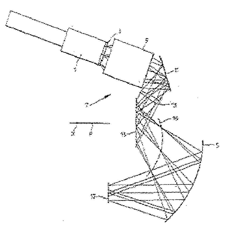
[0035]Referring now to a FIG. 1 of the drawings, there is illustrated a known cathode ray tube (CRT) head mounted display system. The display system is a binocular system and utilises two display systems (only one of which is illustrated in FIG. 1) according to an embodiment of the invention, one for each eye of a user of the system.

[0036]The display system for each eye comprises a miniature CRT 1 comprising a screen 3, upon whi...


PUM


Abstract

A head up display apparatus is disclosed for projecting an image upon a screen. The apparatus comprises a signal processing system, comprising an image projector for projecting an image to a partially reflective screen, the screen being configured substantially in front of an eye of a user of the display apparatus. The apparatus further comprises a beam steering arrangement for steering the projected image substantially at an exit pupil of the system, upon the screen, and a pupil tracking arrangement for tracking a pupil of the users eye such that the projected image remains directed at the pupil of the user as the user adjusts their line of sight.

Description

FIELD OF THE INVENTION[0001]The present invention relates to head up display systems and to head mounted displays, such as helmet mounted display systems, as used by personnel in, for example, medicine, the emergency services, the military and virtual reality gamers for providing hands-free visual data.BACKGROUND TO THE INVENTION[0002]Head-up displays have been common in attack aircraft for several decades, with a CRT or similar located below an inside face of the cockpit windshield with optics suitable for superimposing an image upon said inside face, which serves as a combining mirror. Problems associated with such designs arose from: i) their size and the limited instrument panel space; ii) the displayed information was stationary with respect to an axis, usually aligned along the longitudinal axis of the aircraft; and, iii) the images were presented within a limited field of view. The first modern HMDs were developed in the United Kingdom in the early 1950's; but it was not unti...

Claims


Application Information

Patent Timeline
IPC IPC(8): G09G5/00
CPCG02B27/0101G02B27/0172G02B2027/0187G02B2027/0118G02B2027/0123G02B2027/011
Inventor FREEMAN, JONATHAN PAUL
Owner BAE SYSTEMS PLC
Why Eureka
Try Eureka