
Sensor Element and System Comprising Wide Field-of-View 3-D Imaging LIDAR

a sensor element and wide field of view technology, applied in the field of lidar imaging systems, can solve the problems of not being able to provide an operator at the remote site, limiting the ability of cargo uas to complete the needed phases, and no properly prepared landing si

Inactive Publication Date: 2011-11-24
PFG IP +1
View PDF18 Cites 103 Cited by
  • Summary
  • Abstract
  • Description
  • Claims
  • Application Information

AI Technical Summary

Benefits of technology

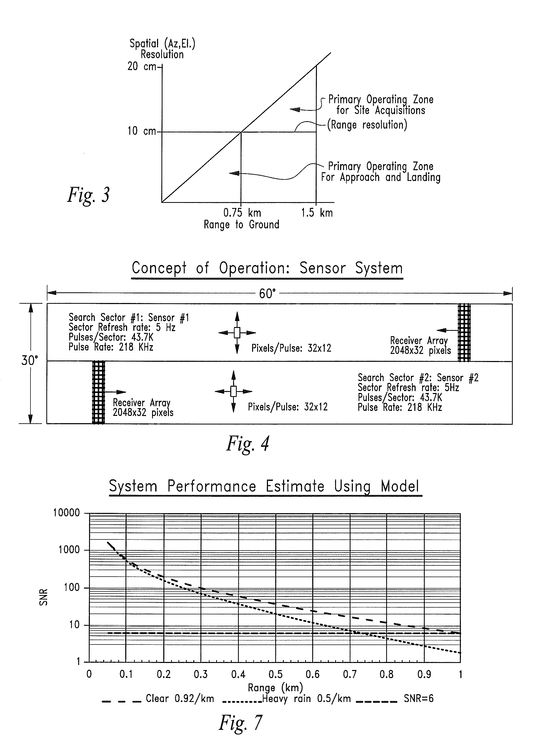
[0044]FIG. 7 is a graph showing estimated

Problems solved by technology

Delivering war materials to fighting forces in a timely manner is a problem that exists at all levels of conflict.
A brief review of prior art UAS cargo operations reveals at least two deficiencies that presently limit the ability of cargo UAS to complete the needed phases of a cargo transport mission.
At forward operating positions though, there typically are no properly prepared landing sites.
In addition, while current UAS can be landed by handing off the landing operation to a skilled operator with line-of-sight (LOS) to the aircraft, there may not be an operator available at the remote site.
However, in many landing situations GPS will degrade or drop out entirely due to terrain occlusions and multi-path GPS signal effects near the ground.

Method used


Image

  • Sensor Element and System Comprising Wide Field-of-View 3-D Imaging LIDAR
  • Sensor Element and System Comprising Wide Field-of-View 3-D Imaging LIDAR
  • Sensor Element and System Comprising Wide Field-of-View 3-D Imaging LIDAR

Examples


Embodiment Construction

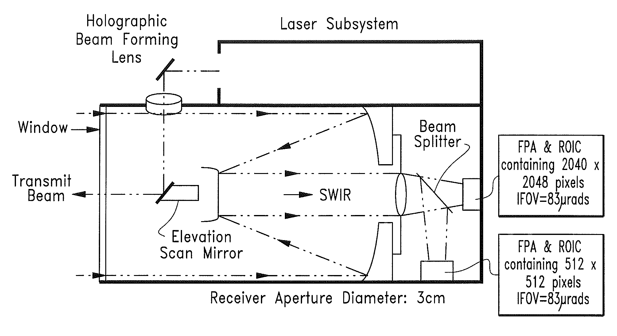
[0047]Turning now to the figures wherein like numerals define like elements among the several views, a UAS autonomous landing sensor system comprising a wide field-of-view 3-D imaging LIDAR is disclosed.

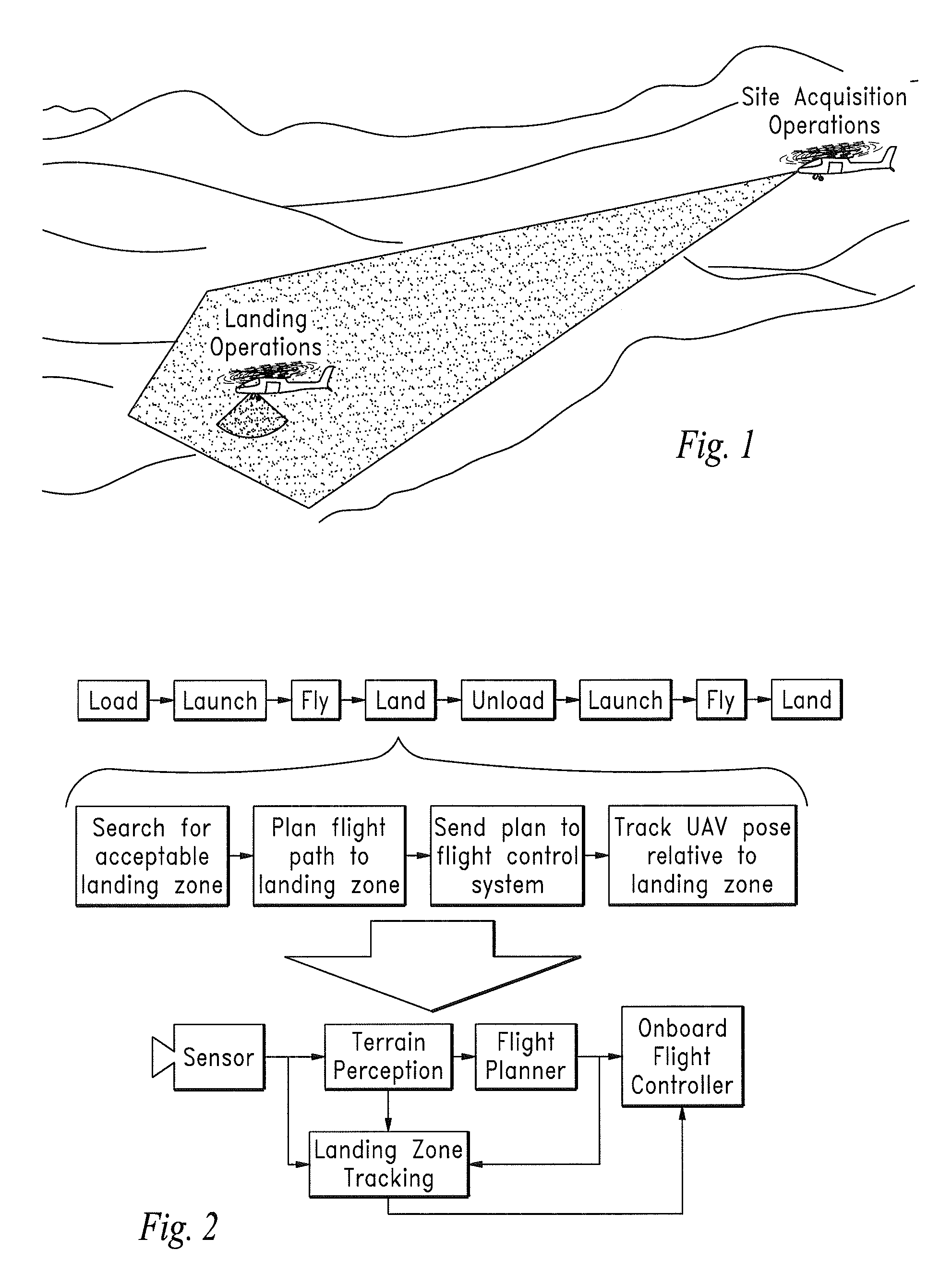
[0048]The UAS autonomous landing approach commonly used in UAS applications is generally illustrated in FIG. 1 showing the UAS surveying potential landing sites using the sensor system of the invention and engaging in an autonomous landing operation at the selected site.

[0049]The invention may comprise state-of-the-art, eye-safe, high pulse rate fiber lasers to achieve rapid, accurate three-dimensional surveillance of potential UAS landing sites.

[0050]Processing algorithms running in suitable electronic circuitry the process the received three-dimensional voxel data from the sensor system to characterize the scenes, select a preferred landing location, and enable the navigation system of the UAS to achieve accurate landing operations under a broad range of operating conditions.

[0051]...


PUM


Abstract

A LIDAR sensor element and system for wide field-of-view applications such as autonomous UAS landing site selection is disclosed. The sensor element and system have an imaging source such as a SWIR laser for imaging a field of regard or target with a beam having a predefined wavelength. The beam is scanned over the field of regard or target with a beam steering device such as Risley prism. The reflected beam is captured by the system by receiving optics which may comprise a Risley prism for receiving and imaging the reflected beam upon a photodetector array such as a focal plane array. The focal plane array may be bonded to and a part of a three-dimensional stack of integrated circuits, a plurality of which may comprise one or more read out integrated circuits.

Description

CROSS-REFERENCE TO RELATED APPLICATIONS[0001]This application claims the benefit of U.S. Provisional Patent Application No. 61 / 395,712, filed on May 18, 2010 entitled “Autonomous Landing at Unprepared Sites for a Cargo Unmanned Air System” pursuant to 35 USC 119, which application is incorporated fully herein by reference.STATEMENT REGARDING FEDERALLY SPONSORED RESEARCH AND DEVELOPMENT[0002]N / ABACKGROUND OF THE INVENTION[0003]1. Field of the Invention[0004]The invention relates generally to the field of LIDAR imaging systems. More specifically, the invention relates to a UAS autonomous landing sensor system comprising a wide field-of-view 3-D imaging LIDAR.[0005]2. Description of the Related Art[0006]Unmanned Air or Aerial Systems (UAS) have revolutionized certain aspects of military operations. Without the need for an onboard flight crew, UAS are able to maintain position for longer periods of time and permit rotations of crews more frequently for increased vigilance. This success ...

Claims


Application Information

Patent Timeline
IPC IPC(8): G01C3/08
CPCG01S7/4813G01S7/4815G01S7/4817G05D1/0676G01S17/88G01S17/89G01S17/87
Inventor JUSTICE, JAMESAZZAZY, MEDHATLUDWIG, DAVID
Owner PFG IP
Learn More