Fiber array unit with integrated optical power monitor

a fiber array unit and optical power monitor technology, applied in the direction of transmission monitoring, instruments, optical elements, etc., can solve the problems of inability to utilize conventional off-the-shelf plc chips, difficult to integrate optical channel monitoring within the optical network, and large size,

Active Publication Date: 2009-01-15
ZHU HAI BEN JIA TECH CO LTD +1
View PDF6 Cites 218 Cited by
  • Summary
  • Abstract
  • Description
  • Claims
  • Application Information

AI Technical Summary

Benefits of technology

[0009]The tapping filter may be a unitary, planar structure at least partially optically transparent, disposed within a slit cut through the substrate and interrupting each transmission chan

Problems solved by technology

Conventional optical channel monitoring in planar waveguide circuits (PLCs) used for fiber-optic communication is usually implemented separately outside of the PLC product packaging; resulting in more complex integration of optical channel monitoring within an optical network.
This results in h

Method used


Image

  • Fiber array unit with integrated optical power monitor
  • Fiber array unit with integrated optical power monitor
  • Fiber array unit with integrated optical power monitor

Examples


Embodiment Construction

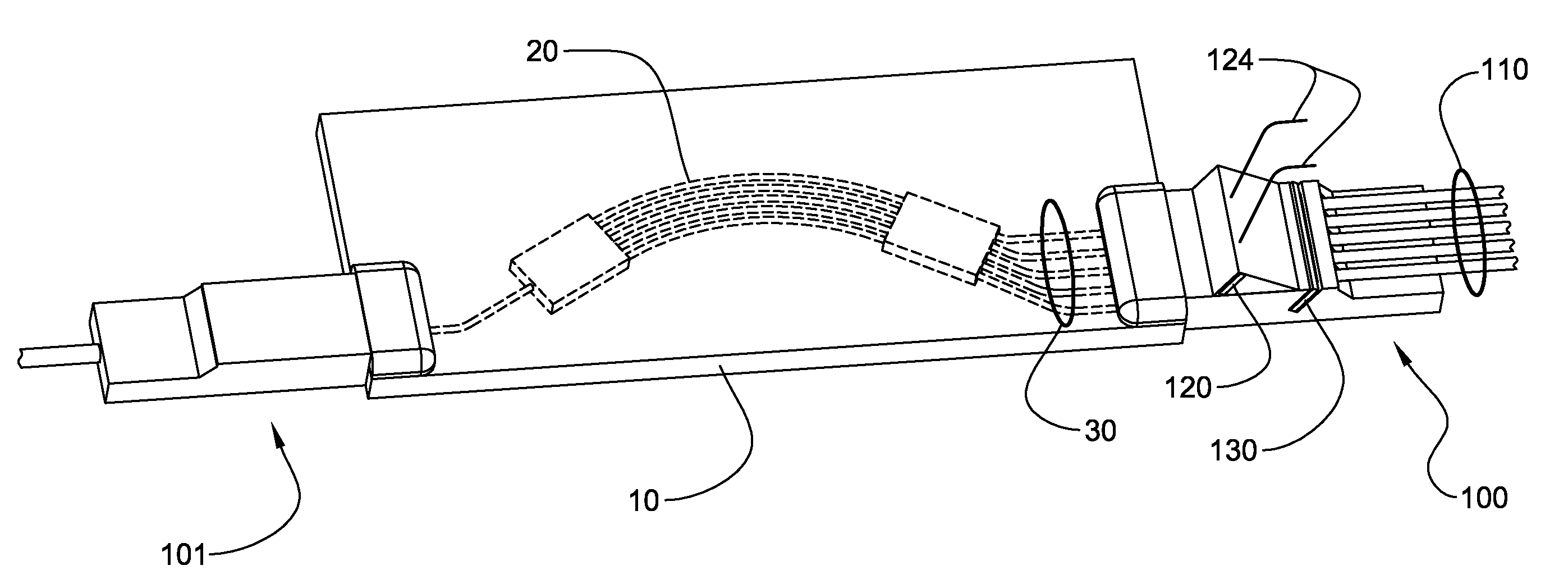
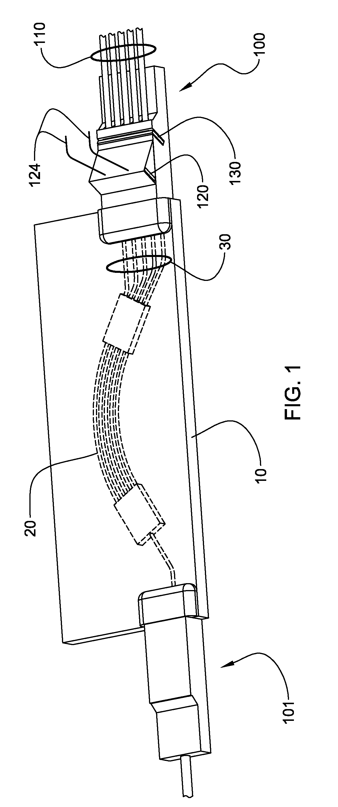
[0017]With reference to FIG. 1, a typical planar waveguide circuit (PLC) 10 is shown, specially designed to implement an exemplary arrayed waveguide grating (AWG) 20, with input and / or output waveguides 30 running toward the edge of the PLC. (AWGs are known in the art, along with many other optical circuits that could be implemented within PLC 10, and to which the present invention can be directed.)

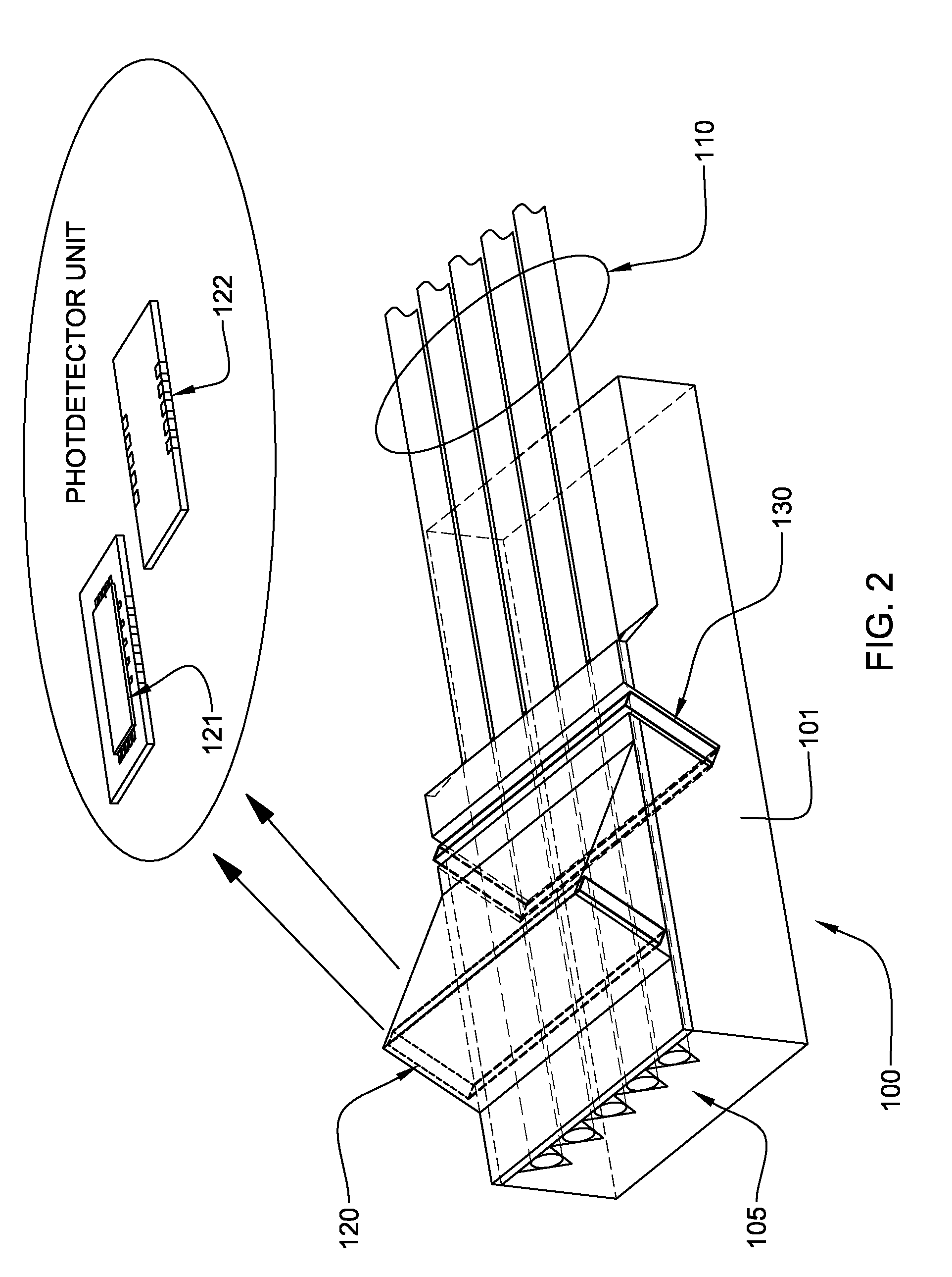
[0018]In accordance with the present invention, fiber array units (FAUs) 100 (and 101) can be attached to the edges of PLC 10, having optical signal transmission channels 110 for carrying optical signals to and / or from the waveguides 30 of PLC 10. Exemplary embodiments of transmission channels include fiber optics, placed in trenches defined within the FAU. As discussed further below, FAU 100 may include a photodetector unit 120 attached thereto, which can be controlled / monitored using anode / cathode pair 130. Photodetector unit 120 monitors at least some of the optical power transmitted w...


PUM


Abstract

A technique for monitoring optical power in a fiber array unit having a plurality of optical transmission waveguides terminating at an edge thereof for carrying optical signals to and/or from a PLC. A tapping filter is placed within a slit formed in the substrate and interrupting the transmission channels, thereby tapping at least some of the optical power from the channels and directing the tapped optical power toward respective photodetector channels for detection, while allowing other optical power to continue transmission in the at least one channel of the fiber array unit.

Description

CROSS-REFERENCE TO RELATED APPLICATION[0001]This application claims the benefit of U.S. Provisional Application No. 60 / 949,259, filed Jul. 12, 2007, which is hereby incorporated herein by reference in its entirety.TECHNICAL FIELD[0002]The present invention relates to an optical power monitoring function integrated into a fiber array unit (FAU), which can be easily assembled in a standard planar lightwave circuit (PLC) component package without jeopardizing quality and reliability.BACKGROUND OF THE INVENTION[0003]Conventional optical channel monitoring in planar waveguide circuits (PLCs) used for fiber-optic communication is usually implemented separately outside of the PLC product packaging; resulting in more complex integration of optical channel monitoring within an optical network. If the optical channel monitoring function is integrated into the PLC components, special PLC design is necessary, and the entire PLC component package should be hermetically sealed to protect against ...

Claims


Application Information

Patent Timeline
IPC IPC(8): G02B6/12H04B10/08
CPCG02B6/12019H04B10/25H04B10/0795G02B6/2852
Inventor ISHIDA, KENZO
Owner ZHU HAI BEN JIA TECH CO LTD
Why Eureka
Try Eureka