Blood inspection device
A blood test, blood technology, applied in the direction of measuring devices, sensors, diagnosis, etc., can solve the problems of poor maintenance and trouble, and achieve the effect of easy discharge
- Summary
- Abstract
- Description
- Claims
- Application Information
AI Technical Summary
Problems solved by technology
Method used
Image

Examples
Embodiment approach 1
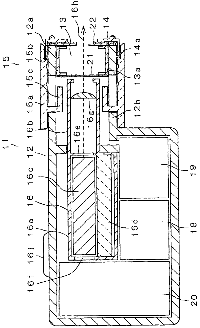
[0039] image 3 It is a cross-sectional view of blood test device 11 according to Embodiment 1 of the present invention. exist image 3 Among them, the case 12 is formed of a resin material, and the case 12 is provided with a cylindrical body 12b having an opening 12a. A filter unit 13 including a filter 21 is mounted inside the cylinder 12b, and a sensor unit 14 including a sensor 22 for analyzing components of body fluid such as blood is mounted outside the cylinder 12b.
[0040] The main body portion 15a of the discharge mechanism 15 is slidably provided outside the cylindrical body 12b. The first discharge part 15b and the second discharge part 15c are formed on the main body part 15a. The first ejection portion 15 b comes into contact with the sensor unit 14 to push out the sensor unit 14 . Furthermore, the second ejection portion 15c comes into contact with the filter unit 13 to push out the filter unit 13 .
[0041] Next, the laser emitting device 16 provided in th...
Embodiment approach 2
[0107] Figure 19 It is a cross-sectional view of blood test apparatus 11-2 according to Embodiment 2 of the present invention. In order to simplify the description, the same reference numerals are attached to the same components as in the first embodiment described above.
[0108] exist Figure 19 Among them, the case 12 is formed of a resin material, and the case 12 is provided with a cylindrical shape 12b having an opening 12a. A filter unit 13 is installed inside the cylinder 12b, and a sensor unit 14 is installed outside the cylinder 12b. The filter unit 13 is equipped with a filter 21, and the sensor unit 14 is equipped with a sensor 22.
[0109] The main body portion 15a of the discharge mechanism 15 is slidably provided outside the cylindrical body 12b. The first discharge part 15b and the second discharge part 15c are formed in the main body part 15a. The first ejection portion 15 b comes into contact with the sensor unit 14 to push out the sensor unit 14 . Furth...
Embodiment approach 3
[0122] Figure 22 It is a cross-sectional view of blood test apparatus 11-3 according to Embodiment 3 of the present invention. In order to simplify the description, the same reference numerals are assigned to the same components as those in Embodiment 1 and Embodiment 2 described above.
[0123] exist Figure 22 Among them, the housing 12 is formed of a resin material, and a cylindrical body 12 b having an opening 12 a is provided on the housing 12 . A filter unit 13 is installed inside the cylinder 12b, and a sensor unit 14 is installed outside the cylinder 12b. The filter unit 13 is equipped with a filter 21, and the sensor unit 14 is equipped with a sensor 22.
[0124] The main body portion 15a of the discharge mechanism 15 is slidably provided outside the cylindrical body 12b. The first discharge part 15b and the second discharge part 15c are formed in the main body part 15a. The first ejection portion 15 b comes into contact with the sensor unit 14 to push out the se...
PUM
 Abstract
Description
Claims
Application Information
 - R&D Engineer
- R&D Manager
- IP Professional
- Industry Leading Data Capabilities
- Powerful AI technology
- Patent DNA Extraction
Browse by: Latest US Patents, China's latest patents, Technical Efficacy Thesaurus, Application Domain, Technology Topic.
© 2024 PatSnap. All rights reserved.Legal|Privacy policy|Modern Slavery Act Transparency Statement|Sitemap