Sensor chip, measuring instrument using same, and blood test device

A sensor chip and sensor technology, applied in the direction of sensors, measuring devices, sampling devices, etc., can solve the problems of cumbersome operations, unoptimized sanitation and safety, and cumbersome processing

Inactive Publication Date: 2012-03-07
PANASONIC HEALTHCARE HLDG CO LTD
View PDF9 Cites 1 Cited by
  • Summary
  • Abstract
  • Description
  • Claims
  • Application Information

AI Technical Summary

Problems solved by technology

[0010] However, in such a conventional method, the following cumbersome work is required
[0011] That is, in order to wipe off the remaining blood 3a, the user must walk with the tissue paper 8a or cleaning cotton 8b, etc.
Moreover, the user must walk with tissue paper 8a or cleaning cotton 8b, etc., to which the remaining blood 3a after wiping off is attached.
Like this, in order to wipe off the remaining blood 3a, it is not preferable for the user to walk with the tissue paper 8a or the cleaning cotton 8b, etc. in terms of hygiene and safety, and its handling is cumbersome.

Method used


Image

  • Sensor chip, measuring instrument using same, and blood test device
  • Sensor chip, measuring instrument using same, and blood test device
  • Sensor chip, measuring instrument using same, and blood test device

Examples


Embodiment approach 1

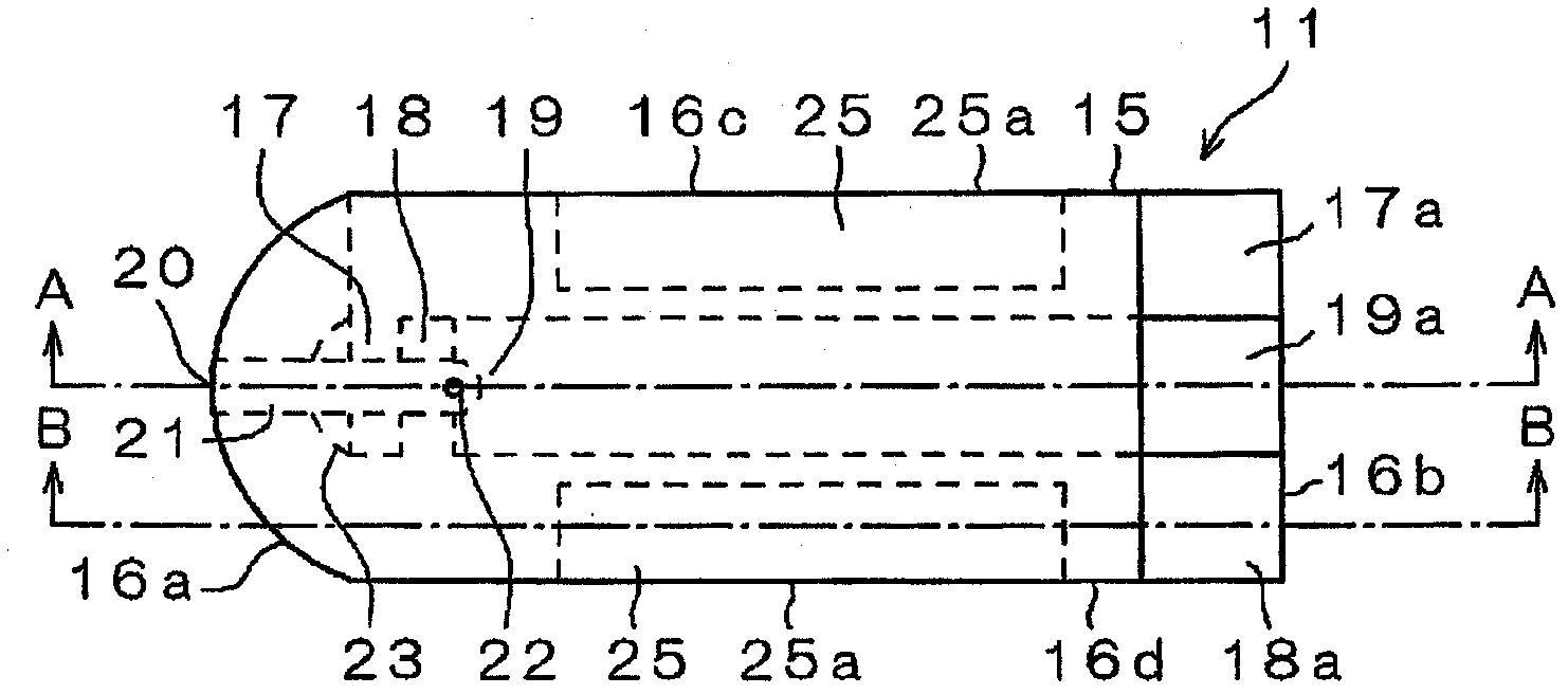
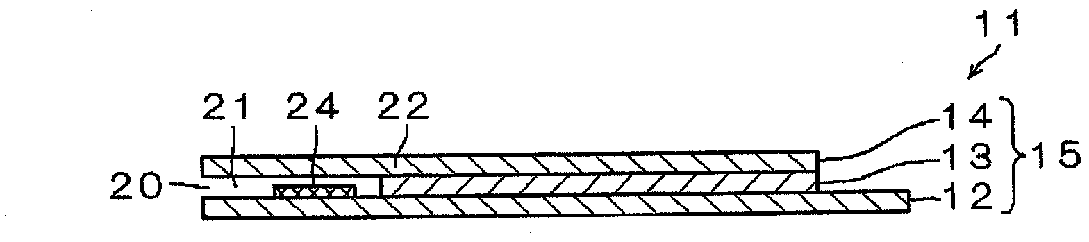
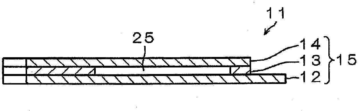
[0064] figure 1 It is a plan view of the sensor chip 11 in the first embodiment. figure 2 yes figure 1 A-A sectional view of, image 3 yes figure 1 The B-B section view. exist figure 1 , figure 2 , image 3 Among them, the sensor chip 11 has a plate shape. and, if figure 2 , image 3 As shown, the sensor chip 11 has a three-layer structure including a substrate 12 , a spacer 13 bonded on the substrate 12 , and a cover 14 bonded on the spacer 13 . That is, the plate-shaped substrate 12 , the spacer 13 and the cover 14 form the base 15 .

[0065] In addition, if figure 1 As shown, the sensor chip 11 has a substantially rectangular shape, and one short side 16 a side has a semicircular shape. Detection electrodes 17 , 18 , 19 are laid on the substrate 12 . The detection electrodes 17, 18, and 19 are formed to extend toward the other short side 16b of the sensor chip 11, and are connected to the connection terminals 17a, 18a, and 19a, respectively.

[0066] T...

Embodiment approach 2

[0100] Next, use Figure 8 ~ Figure 11 The sensor chip 41 in Embodiment 2 (corresponding to the sensor chip 11 in Embodiment 1) will be described.

[0101] Sensor chip 41 in Embodiment 2 differs from Embodiment 1 above in that excess blood reservoir 42 (corresponding to excess blood reservoir 25 in Embodiment 1) is formed on a different layer from supply channel 21 . In addition, in this Embodiment 2, the same code|symbol is attached|subjected to the structure common to Embodiment 1, and description is simplified. In addition, the same applies to the following embodiments.

[0102] Figure 8 It is a plan view of the sensor chip 41 according to the second embodiment. Figure 9 yes Figure 8 C-C cutaway view, Figure 10 yes Figure 8 D-D cross-sectional view.

[0103] Such as Figure 9 , Figure 10 As shown, the sensor chip 41 is formed as a substrate 43 (corresponding to the substrate 12 in Embodiment 1), a spacer 44 bonded on the upper surface of the substrate 43 (cor...

Embodiment approach 3

[0116] Such as Figure 16 As shown, the sensor chip 51 in Embodiment 3 (corresponding to the sensor chip 41 in Embodiment 2) differs from the sensor chip 41 in Embodiment 2 above only in the structure of the remaining blood pool 52 . That is, in order to increase the thickness strength of the excess blood pool 52 , in Embodiment 3, a plurality of convex portions 52 b are provided in the excess blood pool 52 . Accordingly, even when the sensor chip 51 is pressed in the thickness direction, the thickness dimension can be kept substantially constant. In addition, even if a pressing force is applied from the outside in the thickness direction of the excess blood pool 52, the sensor chip 51 will hardly bend in the thickness direction due to the pressing force, so that the excess blood 3a can be prevented from flowing out from the excess blood inflow port 52a. .

[0117] In Embodiment 3, in order to form the remaining blood pool 52, as Figure 12 As shown in (b), the convex porti...


PUM

PropertyMeasurementUnit
thicknessaaaaaaaaaa
thicknessaaaaaaaaaa

Abstract

Disclosed is a sensor chip (11) provided with: a plate-shaped substrate (15); an inlet (20) which is provided in the thickness direction of the substrate (15) and into which blood (3) to be measured flows; a supply channel (21) connected to the inlet (20); and detection electrodes (17, 18, 19) provided on the supply channel (21). The substrate (15) is provided with an excess blood collection section (25) that suctions excess blood (3a) and stores the suctioned excess blood (3a).

Description

technical field [0001] The present invention relates to a sensor chip for measuring blood sugar level and the like, a measuring device and a blood test device using the sensor chip. Background technique [0002] Hereinafter, a conventional sensor chip and a blood test method using the sensor chip will be described. [0003] Diabetic patients need to regularly measure blood sugar levels and inject insulin according to the blood sugar levels to maintain normal blood sugar levels. For this purpose, the patient collects a small amount of blood from a fingertip or the like, and uses the collected blood to measure the blood sugar level. In order to detect the blood sugar level, a sensor chip 1 is required (refer to Figure 43 ). [0004] The sensor chip 1 has a substrate 2, an inlet 4, a supply path (not shown), a detection electrode 4b provided in the supply path 4a, and an air hole 4c provided at the end of the supply path 4a. The base body 2 has a substantially rectangular s...

Claims


Application Information

Patent Timeline
Patent Type & Authority Applications(China)
IPC IPC(8): G01N27/28A61B5/151A61B5/157G01N1/10G01N27/327G01N27/416
CPCA61B5/14532A61B5/1486A61B5/150022A61B5/150099A61B5/150213A61B5/150274A61B5/150358A61B5/15113A61B5/15134A61B5/15138A61B5/15174A61B5/157G01N27/3272G01N35/1016G01N2035/1062A61B5/150183A61B5/1411G01N27/26G01N27/283G01N27/307G01N27/4166G01N33/49G01N2400/00
Inventor 藤原雅树
Owner PANASONIC HEALTHCARE HLDG CO LTD
Why Eureka
Try Eureka