
Method for measuring inclination angle of lens module

A lens module and tilt angle technology, which is applied to measurement devices, instruments, optical devices, etc., can solve the problems of complex measurement methods and long measurement periods, and achieve the effect of simple measurement methods and short measurement periods.

Inactive Publication Date: 2009-11-25
HONG FU JIN PRECISION IND (SHENZHEN) CO LTD +1
View PDF0 Cites 8 Cited by
  • Summary
  • Abstract
  • Description
  • Claims
  • Application Information

AI Technical Summary

Problems solved by technology

The measurement method is complex and the measurement cycle is long

Method used


Image

  • Method for measuring inclination angle of lens module
  • Method for measuring inclination angle of lens module
  • Method for measuring inclination angle of lens module

Examples


Embodiment Construction

[0012] The embodiments of the present invention will be further described in detail below in conjunction with the accompanying drawings.

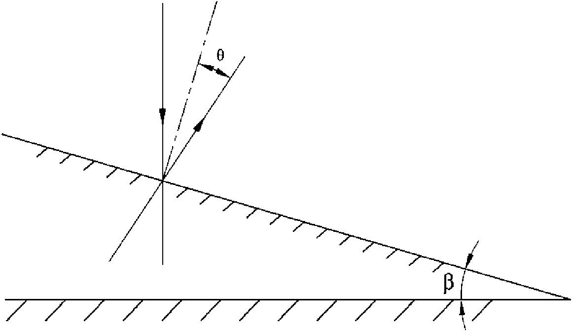
[0013] see figure 1 The method for measuring the inclination angle of the lens module provided by the embodiment of the present invention mainly applies the principle of optical reflection, and the inclination angle between the two planes is obtained by measuring the reflection angles of the laser light passing through two planes respectively. It can be understood that if the reflection angle of one of the planes is zero degrees and the reflection angle of the other plane is θ, then the inclination angle of the two planes is also θ.

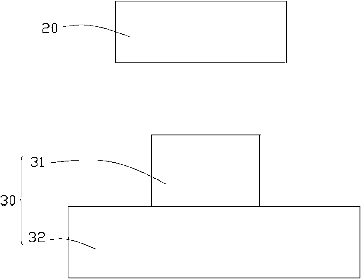
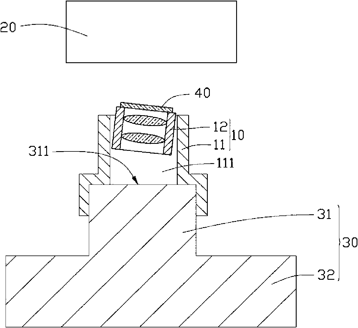
[0014] see figure 2 , image 3 and Figure 4 The lens module 10 to be tested includes a lens mount 11 and a lens barrel 12 , the lens mount 11 has an accommodating cavity 111 , and the lens barrel 12 is accommodated in the accommodating cavity 111 . The method for measuring the inclination angle of the le...


PUM


Abstract

The invention discloses a method for measuring an inclination angle of a lens module, which comprises the following steps: providing a measuring device; providing a standard fixture which comprises a cylinder provided with a reflecting surface capable of reflecting laser; aligning the measuring device to the reflecting surface, emitting laser to the reflecting surface, and regulating relative positions of the standard fixture and the measuring device until a reflection angle of the laser is zero; fixing the lens module onto the standard fixture and making the reflecting surface positioned on a plane reserved for mounting an image sensor in the lens module; providing a horizontal reflecting mirror, and placing the horizontal reflecting mirror on an end face of one end of a lens barrel of the lens module, wherein the end is far away from the standard fixture; emitting the laser to the reflecting mirror to measure the reflection angle of the laser; and calculating the inclination angle of the lens module relative to the plane reserved for mounting the image sensor. The method for measuring the inclination angle of the lens module measures the inclination angle of the lens module relative to the plane reserved for mounting the image sensor by a geometric optical means.

Description

technical field [0001] The invention relates to a method for measuring an inclination angle of a lens module. Background technique [0002] Since the first day of its appearance, digital cameras have been loved by people because they can be directly digitized. The shooting process of digital cameras is to directly convert optical signals into electrical signals through image sensors for digital storage. (Please refer to "ABC of Digital Camera", China Audio-visual Education, 2002, 12.80-82) [0003] However, the camera module manufacturing, maintenance and assembly process is easily affected by component manufacturing and assembly errors, resulting in the phenomenon that the optical axes of the image sensor and the lens module are not perpendicular. This situation will lead to uneven illuminance of the incident light received by the image sensor, resulting in out-of-focus of the imaging corner of the camera module, so that the obtained image will be uneven. Therefore, it is...

Claims


Application Information

Patent Timeline
Patent Type & Authority Applications(China)
IPC IPC(8): G01B11/26
Inventor 陈汉邦
Owner HONG FU JIN PRECISION IND (SHENZHEN) CO LTD
Learn More