
Method and key circuit for measuring solution conductivity through triangular wave excitation
A measurement method, triangular wave technology, applied in the direction of material resistance, etc., can solve problems such as theoretical errors, and achieve the effect of less calculation, simple excitation signal, and simple measurement and calculation methods
- Summary
- Abstract
- Description
- Claims
- Application Information
AI Technical Summary
Problems solved by technology
Method used
Image

Examples
Embodiment 1
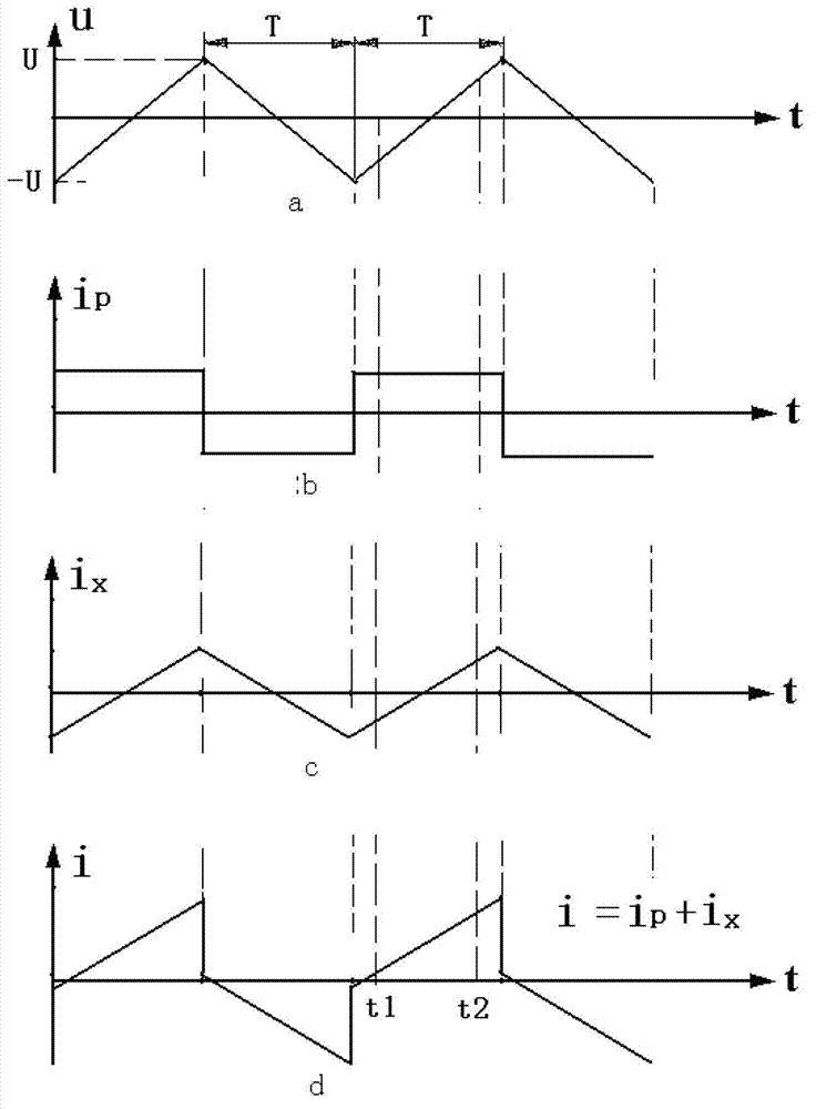
[0061] When testing, place the electrode in the solution to be tested, and use an AC symmetrical triangular wave voltage signal with a voltage amplitude of U and a period of 2T to excite the electrode, and remove peaks and troughs in the upper or lower band of the excitation voltage signal. The current signal of the electrode response is sampled at any two different moments t1 and t2, and the sampling values of the two current signals are respectively i t1 and i t2 , using the expression R x =|2U(t2-t1) / (T(i t2 -i t1 ))|Obtain the resistance value Rx of the solution to be measured.
Embodiment 2
[0063] When testing, place the electrode in the solution to be tested, and use an AC symmetrical triangular wave voltage signal with a voltage amplitude of U and a period of 2T to excite the electrode, and remove peaks and troughs in the upper or lower band of the excitation voltage signal. The current signal of the electrode response is sampled at any two different moments t1 and t2, and the sampling values of the two current signals are respectively i t1 and i t2 ; Also sample the excitation voltage signals at time t1 and t2, and the sampling values of the two voltage signals are respectively u t1 and u t2 , using the expression R x =(u t2 -u t1 ) / (i t2 -i t1 ) to obtain the resistance value R of the solution to be measured x .
Embodiment 3
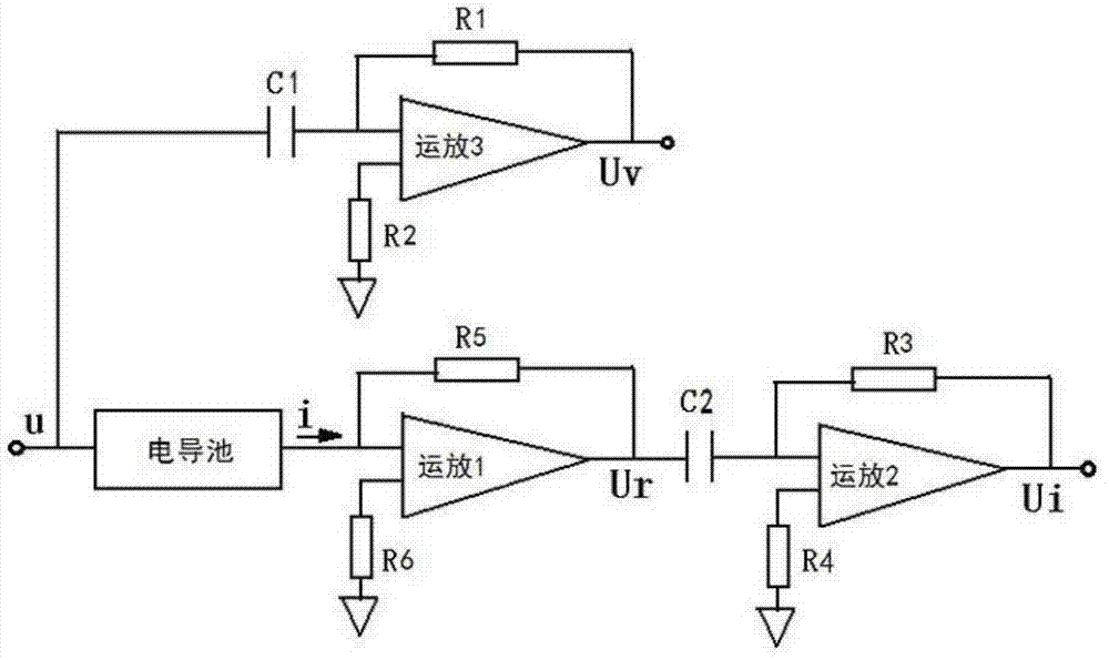
[0065] During detection, put the electrode into the solution to be tested, and use an AC symmetrical triangular wave voltage signal with a voltage amplitude of U and a period of 2T to excite the electrode. figure 2 The circuit shown detects the change rate of the excitation voltage signal and the change rate of the electrode-responsive current signal, and divides the change rate of the excitation voltage signal by the change rate of the electrode-responsive current signal by the follow-up circuit to obtain the solution to be measured. Resistance R x ;
[0066] In the above embodiments, the AC symmetrical triangular wave used refers to a triangular wave in which the peaks and troughs of the triangular wave have opposite polarities, equal amplitudes, and the absolute values of the slopes of the upper and lower bands are equal.
PUM
 Abstract
Description
Claims
Application Information