
Reactive power compensation control method of three-phase unbalance system

A technology of balanced system and compensation control, which is applied in the direction of reactive power compensation, reactive power adjustment/elimination/compensation, multi-phase network asymmetry reduction, etc., which can solve the problem of increasing line loss, three-phase voltage asymmetry, and reducing power distribution Transformer output and other issues

Inactive Publication Date: 2009-11-25
东方博沃(北京)科技有限公司
View PDF3 Cites 13 Cited by
  • Summary
  • Abstract
  • Description
  • Claims
  • Application Information

AI Technical Summary

Problems solved by technology

[0002] Three-phase voltage or current asymmetry will cause a series of hazards to power generation, transmission, distribution equipment and electrical equipment in the power system: increased line loss, increased active loss of distribution transformers, and reduced output of distribution transformers , causing three-phase voltage asymmetry, affecting the output power of the motor, and increasing the temperature of the winding

Method used


Image

  • Reactive power compensation control method of three-phase unbalance system
  • Reactive power compensation control method of three-phase unbalance system
  • Reactive power compensation control method of three-phase unbalance system

Examples


Embodiment Construction

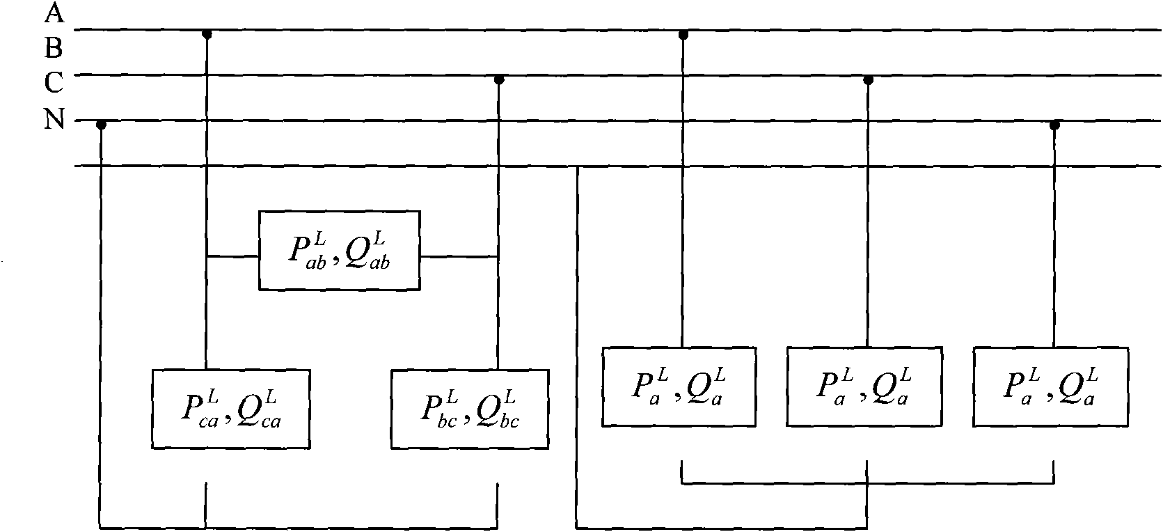
[0060] The load is represented by active power and reactive power, the actual three-phase unbalanced system can be equivalent to figure 1 System shown:

[0061] Assume figure 1 The active power of the system is P a , P b , P c , The system reactive power is Q a , Q b , Q c . Can be assumed P ab L = P bc L = P ca L = P x , Q ab L = Q bc L = Q ca L = Q x . In this way, the active power and reactive power of the system can be expressed as:

[0062] P a = P ab ...


PUM


Abstract

The invention relates to a reactive power compensation control method of three-phase unbalance system, comprises steps of: taking pressure or current of three-phase pressure or current to count reactive power Qa, Qb, Qc and active power Pa, Pb and Pc, respectively; setting and counting a Y compensatory part Qa, Qb, Qc required by a load Delta connection part and a Y compensatory part Qab, Qbc, Qca required by a load Y connection part and then obtaining a compensation formula; making three-phase power factor close to 1 and making three-phase reactive current balance to reduce usage quantity of capacitance, adjusting Q to make compensation effect and capacitance arrangement reach optimum; comparing and judging the reactive power of the three-phase unbalance system and counting scope, and compensating capacitance of the reactive power of the three-phase unbalance system. Using the system and the method provided by the invention, asymmetric loads are scattered into different outlet points to reduce out of limits of asymmetry caused by centralized connection.

Description

Technical field [0001] The invention relates to a reactive power compensation control method of a three-phase unbalanced system, belonging to the field of AC mains or AC power distribution networks. Background technique [0002] The asymmetry of the three-phase voltage or current will cause a series of harms to the power generation, transmission, distribution equipment and electrical equipment in the power system: increase the line loss, increase the active loss of the distribution transformer, and reduce the output of the distribution transformer , Cause the three-phase voltage asymmetry, affect the motor output power, and increase the winding temperature. In order to reduce the three-phase asymmetry of the system caused by the asymmetric load, the asymmetric load should be distributed to different power supply points to reduce the problem of excessive asymmetry caused by the centralized connection. The asymmetric load should also be distributed to each phase reasonably and try ...

Claims


Application Information

Patent Timeline
IPC IPC(8): H02J3/18H02J3/26
CPCY02E40/50Y02E40/30
Inventor 李奕李兰芳王建光秦玲
Owner 东方博沃(北京)科技有限公司
Learn More