Piston cooling structure

A technology of piston cooling and structure, applied in the direction of engine components, machine/engine, engine lubrication, etc., can solve the problems of poor workability, not necessarily excellent workability, etc., and achieve the effect of simple structure

Inactive Publication Date: 2009-12-16
AICHI MASCH IND CO LTD
View PDF1 Cites 5 Cited by
  • Summary
  • Abstract
  • Description
  • Claims
  • Application Information

AI Technical Summary

Problems solved by technology

[0005] However, in the above-mentioned piston cooling structure, the oil injection hole must be processed obliquely toward the cylinder bore, and the workability is not necessarily good. When the oil injection hole is formed toward two adjacent cylinder holes, the workability is even worse.

Method used


Image

  • Piston cooling structure
  • Piston cooling structure
  • Piston cooling structure

Examples


Embodiment Construction

[0031] Next, the best mode for carrying out the present invention will be described using examples.

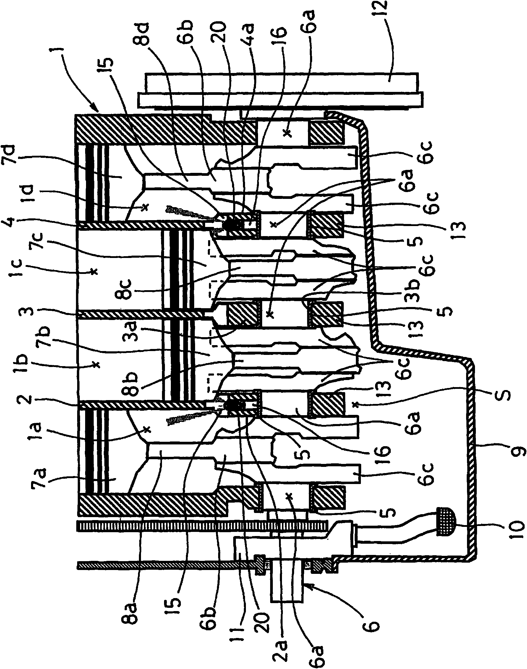
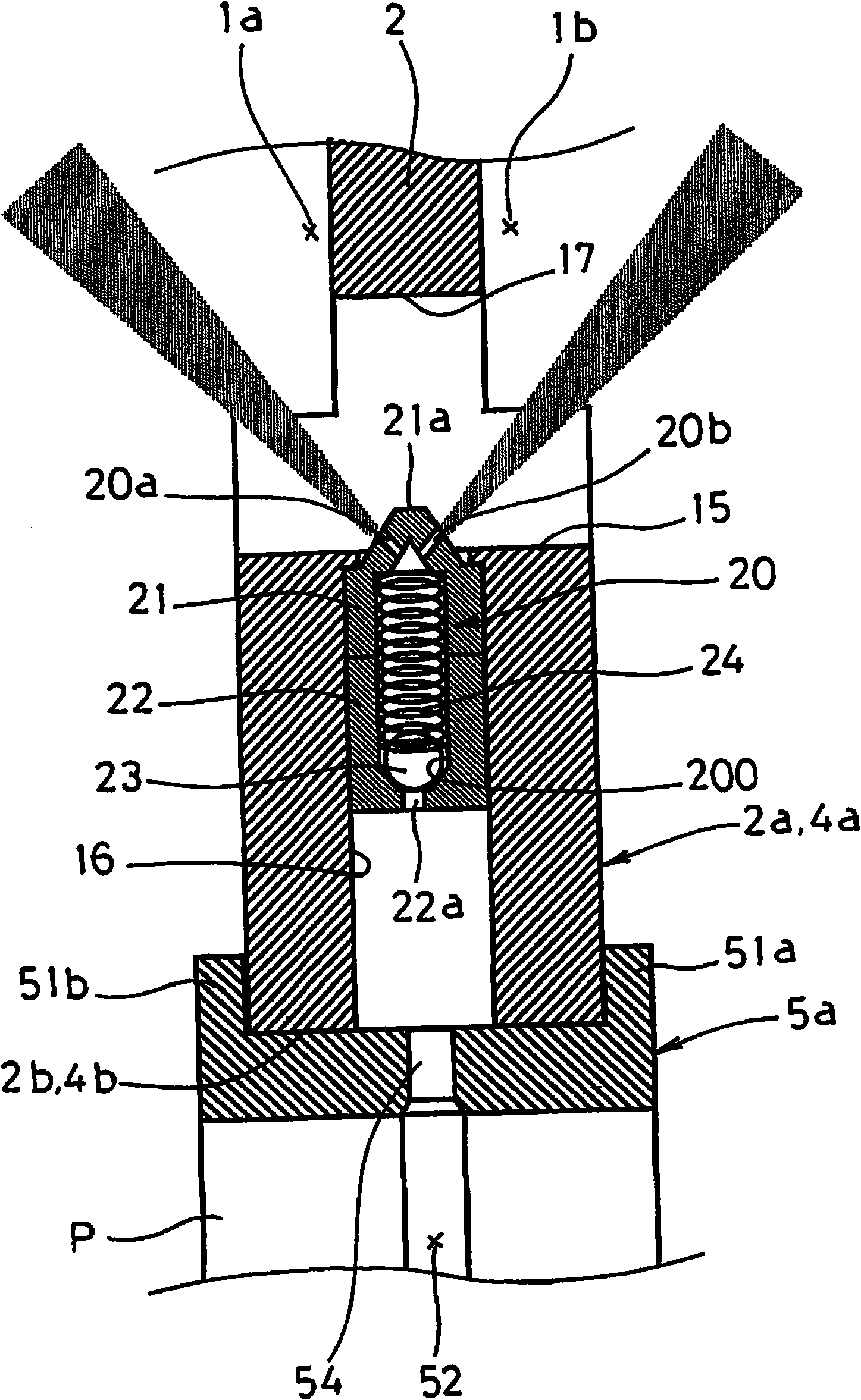
[0032] figure 1 It is a longitudinal sectional structural diagram of the crankcase of a 4-cylinder in-line engine, figure 2 It is a partial enlarged view of the inter-hole walls 2 and 4.

[0033] Such as figure 1 As shown, a crankshaft 6 is rotatably provided in the crankcase 1, and a first cylinder bore 1a, a second cylinder bore 1b, and a cylinder bore 1 are arranged side by side along the axial direction of the crankshaft 6 from left to right in the figure. No. 3 cylinder bore 1c and No. 4 cylinder bore 1d are provided in each cylinder bore 1a, 1b, 1c, and 1d so as to be slidable in the up and down directions respectively, and are connected to the crankshaft 6 through each connecting rod 8a, 8b, 8c, 8d. The 1st piston 7a, the 2nd piston 7b, the 3rd piston 7c, the 4th piston 7d.

[0034] In this example, the inter-hole wall 2 between the first cylinder hole 1a and the sec...


PUM


Abstract

The invention provides a piston cooling structure capable of simply ensuring a structure for spraying oil to the piston. The piston cooling structure uses an oil spraying device (20) to spray oil in order to cool a piston sliding in cylinder bores (1a, 1b) formed on the crank chamber, wherein a bearing portion (2b) is formed on the inter-bore wall (2) between the cylinder bores (1a, 1b). A through opening (15) extending along the axial direction of the crankshaft, and an internal passageway (16) extending to the through opening (15) in a direction parallel to center reciprocation axes are formed on the inter-bore wall (2). As a result, the oil spraying device (20) is accommodated in the internal passageway (16) so that the spraying portions (20a, 20b) are opposite to the through opening (15), and oil is sprayed from the spraying portions (20a, 20b) to the pistons in the cylinder bores (1a, 1b) on both sides.

Description

technical field [0001] The present invention relates to a piston cooling structure that cools and lubricates a piston by spraying lubricating oil toward the piston. Background technique [0002] Conventionally, as such a piston cooling structure, as disclosed in Patent Document 1, a structure in which oil is sprayed from an oil nozzle toward the inner side of the piston to cool and lubricate the piston has been proposed. [0003] In this piston cooling structure, as the oil nozzle, only the oil injection hole penetrating from the inner peripheral surface of the crankshaft bearing part of the cylinder block to the inner wall surface of the cylinder bore is formed, so the direction of oil injection and the design of the lubrication position can be relatively freely selected. High degree of freedom. Furthermore, when the oil injection holes are formed toward two adjacent cylinder holes, oil can be injected toward adjacent pistons at one time. [0004] Patent Document 1: Japan...

Claims


Application Information

Patent Timeline
Patent Type & Authority Applications(China)
IPC IPC(8): F01M1/08F01M1/06
Inventor 益田隆文嵯峨田宗博
Owner AICHI MASCH IND CO LTD
Why Eureka
Try Eureka