
Optical acquisition module signal processing method

An acquisition module and signal processing technology, applied in the field of signal processing

Inactive Publication Date: 2012-02-01
KYE SYST CORP
View PDF8 Cites 0 Cited by
  • Summary
  • Abstract
  • Description
  • Claims
  • Application Information

AI Technical Summary

Problems solved by technology

[0007]The current pointing device that integrates fingerprint identification and displacement signal control solves the problem of hardware cost, but ignores that fingerprint identification and displacement information do not need to be used in practical applications. At the same time, the fingerprint image is captured and then calculated according to the fingerprint identification or displacement signal control, resulting in the complexity of the system calculation

Method used


Image

  • Optical acquisition module signal processing method
  • Optical acquisition module signal processing method
  • Optical acquisition module signal processing method

Examples


Embodiment Construction

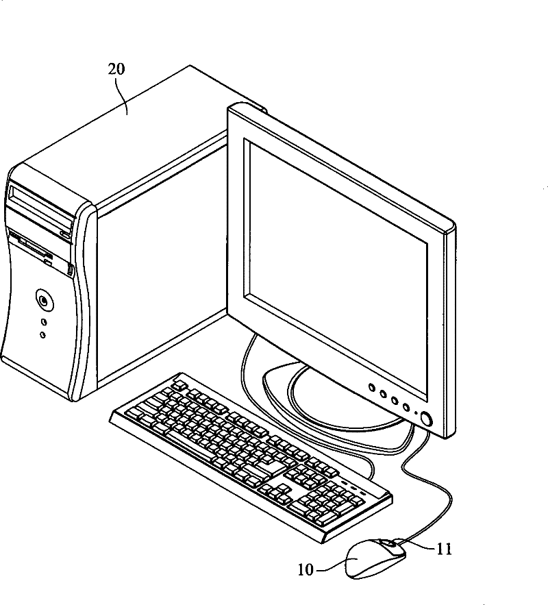
[0022] The signal processing method of the optical capture module disclosed according to the present invention can be installed on a hardware device and the hardware device is connected to a computer device, or the optical capture module can be directly installed on a computer device, wherein the hardware device can be It is an external computer peripheral device such as a mouse, a writing pad, and a trackball. The computer device can be a data processing device such as a desktop computer, a notebook computer, or a personal digital processor. In the following description of the embodiments, a mouse is used as a hardware device, and a desktop computer is used as a computer device, as the best embodiment of the present invention.

[0023] See figure 1 As shown, according to the optical capture module signal processing method disclosed in the present invention, the hardware device 10 is a mouse, and the computer device 20 is a desktop computer. In the known technology, the mouse can...


PUM


Abstract

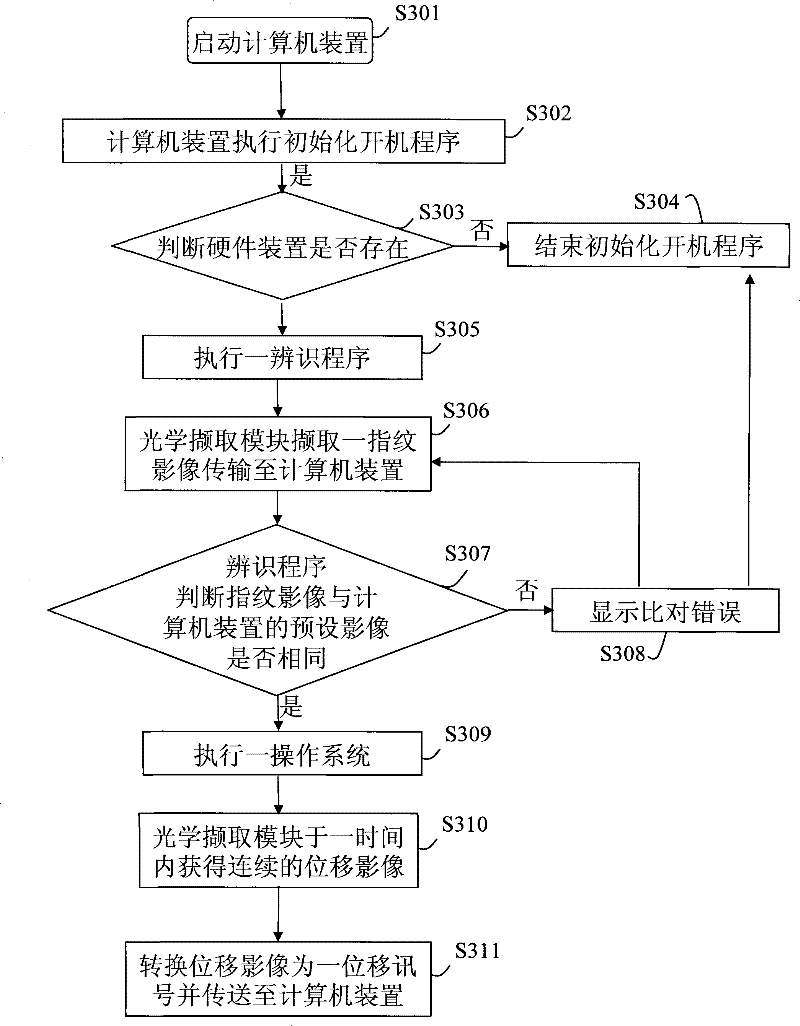
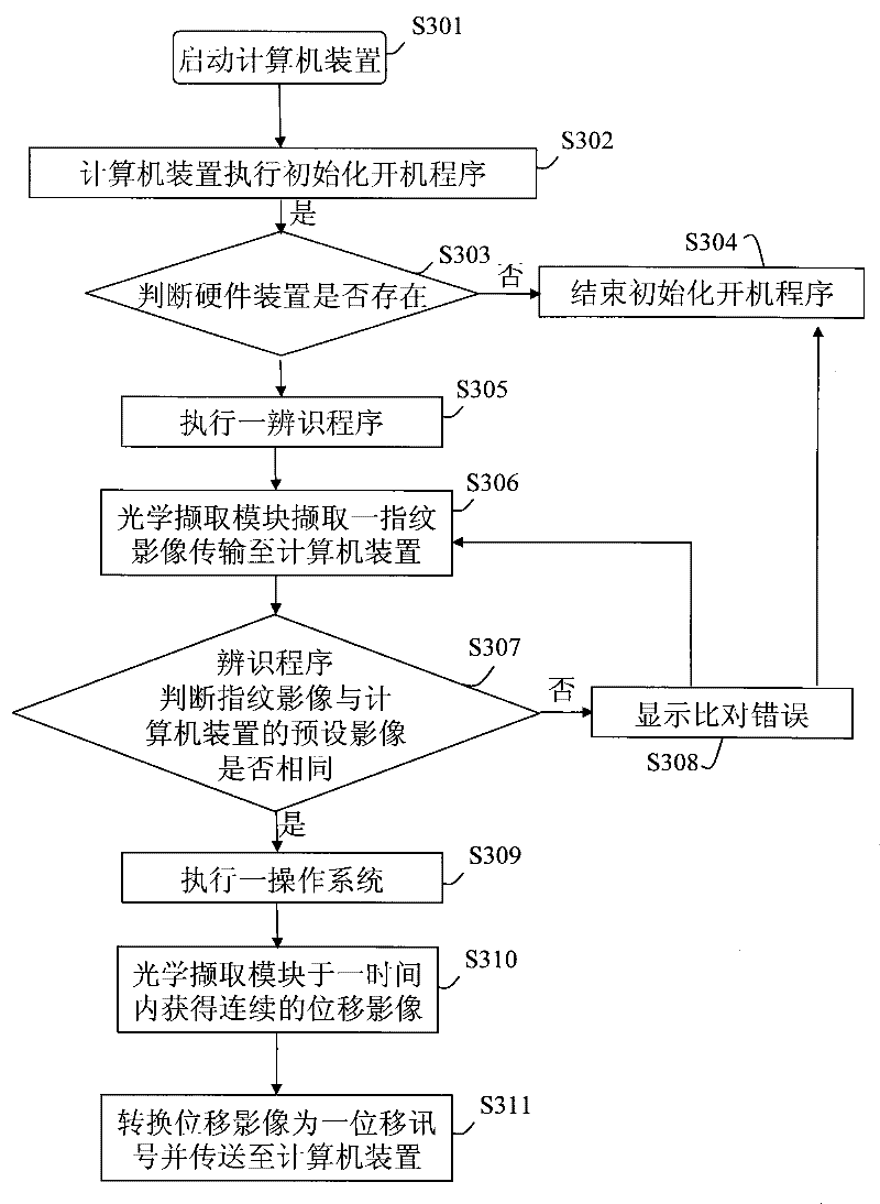
A signal processing method for an optical capture module is that after a hardware device is signal-connected to a computer device, the optical capture module of the hardware device is used to perform fingerprint identification and start-up action, and then enter into continuous image detection to perform displacement control. Confirm the existence of the hardware device through the computer device booting program, and then capture a single fingerprint image through the optical capture module of the hardware device to perform boot-up identification, and then complete the boot and then continuously capture multiple frames of displacement images through the optical capture module and convert them into The displacement signal is sent to the computer device to control the window interface.

Description

Technical field [0001] The present invention is a method of signal processing, especially a method of retrieved image processing for optical capture modules. Background technique [0002] Pointing Device refers to the hardware device (such as personal computers, laptop computers, personal digital assistants, etc.) input coordinate shift signals (such as personal computers, laptops, or personal digital assistants, etc.). There are many types of indicators, such asMouse, trajectory ball device, touchpad, handwriting board, game rod, etc. are all belonging to it.Among them, the mouse can input the computer device input coordinate shift signal according to the user's movement, and there is also a rolling wheel on the mouse. The roller can also control the vertical rolling bar or horizontal scroll bar of the window -based interface. Therefore, on the application windowization systemThe mouse has become the most popular human -machine interface. [0003] After the mouse becomes the mos...

Claims


Application Information

Patent Timeline
Patent Type & Authority Patents(China)
IPC IPC(8): G06F3/01G06K9/00
Inventor 苏玉泉
Owner KYE SYST CORP
Learn More