
Fault-tolerant mechanism optimised for peer to peer network

A peer-to-peer network, node technology, applied in the network field, can solve problems such as being unsuitable for fault tolerance

Inactive Publication Date: 2014-12-24
ALCATEL LUCENT SAS
View PDF2 Cites 0 Cited by
  • Summary
  • Abstract
  • Description
  • Claims
  • Application Information

AI Technical Summary

Problems solved by technology

[0016] However, in practice, the technical problem of fault tolerance has always existed
[0019] Therefore, existing techniques are not suitable for providing sufficient fault tolerance

Method used


Image

  • Fault-tolerant mechanism optimised for peer to peer network
  • Fault-tolerant mechanism optimised for peer to peer network
  • Fault-tolerant mechanism optimised for peer to peer network

Examples


Embodiment Construction

[0032] First, the peer-to-peer network and management device will be described, followed by the application within the communication unit.

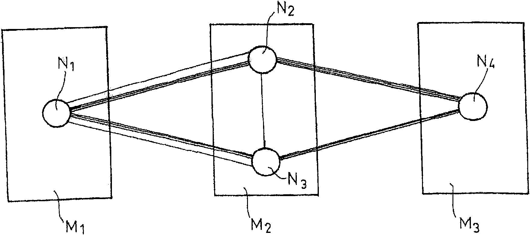
[0033] figure 2 A peer-to-peer network is shown, deployed on a network comprising 3 processing devices M1, M2 and M3. The peer-to-peer network includes a set of nodes N1, N2, N3 and N4 arranged in a ring such that each node has a unique successor node (and a unique predecessor node).

[0034] Attached to this peer-to-peer network is a management device, which notably includes admission means. These admission devices are responsible for inserting new nodes within the peer-to-peer network. Upgradability is an essential property of peer-to-peer networks, in the sense that nodes can be added or removed at any time and the network must be designed to be self-organizing.

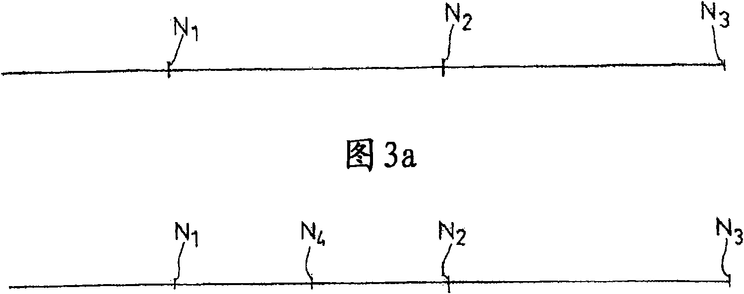
[0035] If we assume that the network includes nodes N1, N2 and N3 at a given time, the admission of a new node N4 consists in determining the position of the entering nod...


PUM


Abstract

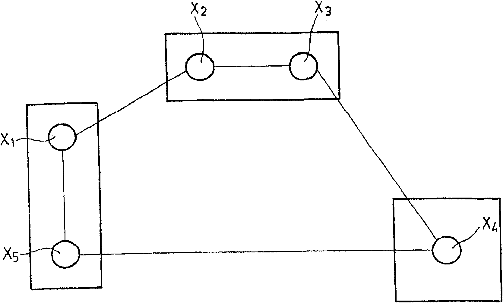
#CMT# # / CMT# The device has an admission unit i.e. admission component, for inserting a new node within a peer-to-peer network (Np2p) of a communication element (E1) e.g. application server in a communication architecture, where the network is composed of nodes (N1-N5). The admission unit determines the adjacent nodes deployed on a same processing equipment, and inserts the new node between the nodes. The nodes (N1-N5) are arranged in circular form such that each node possesses a single successor node and a single predecessor node. #CMT# : # / CMT# An independent claim is also included for a communication element comprising a peer-to-peer network. #CMT#USE : # / CMT# Device for managing a peer-to-peer network of a communication element (claimed) e.g. application server in a communication architecture i.e. Internet protocol multimedia subsystem architecture, or signaling element e.g. proxy conforming to a session initiation protocol defined by Request for Comments (RFC) 3261 of Internet Engineering Task Force (IETF), or call session control function within the architecture. #CMT#ADVANTAGE : # / CMT# The device is configured such that two of the nodes are not present in the same processing equipment, thus limiting the simultaneous failure of the nodes, while eliminating the need for changing fault-tolerant mechanisms. #CMT#DESCRIPTION OF DRAWINGS : # / CMT# The drawing shows a schematic view of a communication element. E1, E2 : Communication equipments LB : Load distribution module Np2p : Peer-to-peer network N-TEL : Communication network N1-N5 : Nodes.

Description

technical field [0001] The invention relates to the deployment of a peer-to-peer network on a set of processing devices. More specifically, the invention relates to the use of these peer-to-peer networks for communication applications. Background technique [0002] In particular it is known to distribute certain telecommunication applications over a group of processing nodes. In this way, each node handles only the portion of requests addressed to the application, and the number of nodes can be adjusted dynamically (if necessary) based on the resources required to handle those requests. This architecture also means that applications can easily be fault-tolerant through the inherent redundancy between nodes. [0003] However, for some applications, there is still the location of contextual information within the set of nodes. Certain applications, such as a signaling unit may require context to be stored between two messages it sends. This context can be used to process s...

Claims


Application Information

Patent Timeline
Patent Type & Authority Patents(China)
IPC IPC(8): H04L29/08H04L12/24H04L69/40
CPCH04L67/1046H04L69/40H04L67/104H04L41/0893
Inventor D·通布罗夫P·德罗普
Owner ALCATEL LUCENT SAS
Learn More