Automatic door closing device

A technology of automatic door closing and housing, applied in the field of door closers, which can solve the problems of general products without suitable structure, intermittent contact between gear and rack, and large backlash

Inactive Publication Date: 2010-01-06
TAIWAN FU HSING INDAL
View PDF0 Cites 5 Cited by
  • Summary
  • Abstract
  • Description
  • Claims
  • Application Information

AI Technical Summary

Problems solved by technology

[0002] The door closer is mainly used to provide a damping effect on the door panel, so that the door panel has a cushioning effect when it is closed, and the elastic element installed inside the door closer can store energy when compressed, so that it can automatically pull slowly when the external force is removed from the door panel The door panel is restored and closed, such as China Taiwan Patent No. 428658, which uses gears, racks and springs to realize the action of the door closer. However, there will be backlash when the gear and the rack of the door closer are meshed. The backlash will increase due to wear and tear, causing intermittent contact between the gear and the rack, causing the door closer to not operate smoothly
[0003] It can be seen that the above-mentioned existing door closer obviously still has inconvenience and defects in structure and use, and needs to be further improved urgently.
In order to solve the above-mentioned problems, the relevant manufacturers have tried their best to find a solution, but for a long time no suitable design has been developed, and the general product has no suitable structure to solve the above-mentioned problems. This is obviously the relevant industry. Urgent problem

Method used


Image

  • Automatic door closing device
  • Automatic door closing device
  • Automatic door closing device

Examples


Embodiment Construction

[0066] In order to further explain the technical means and effects of the present invention to achieve the intended purpose of the invention, the specific implementation, structure, characteristics and effects of the automatic door closer proposed according to the present invention will be described below in conjunction with the accompanying drawings and preferred embodiments. Details are as follows.

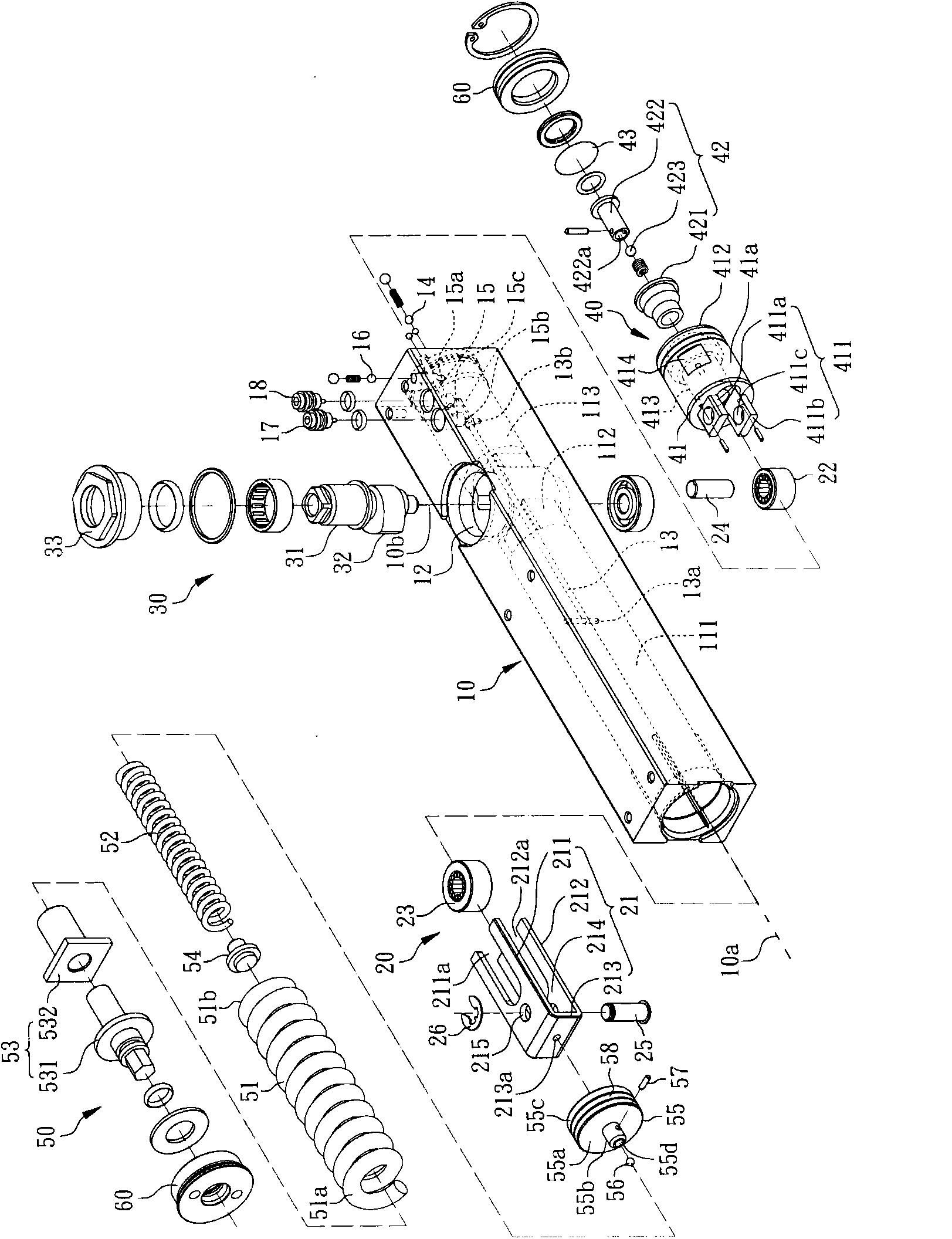
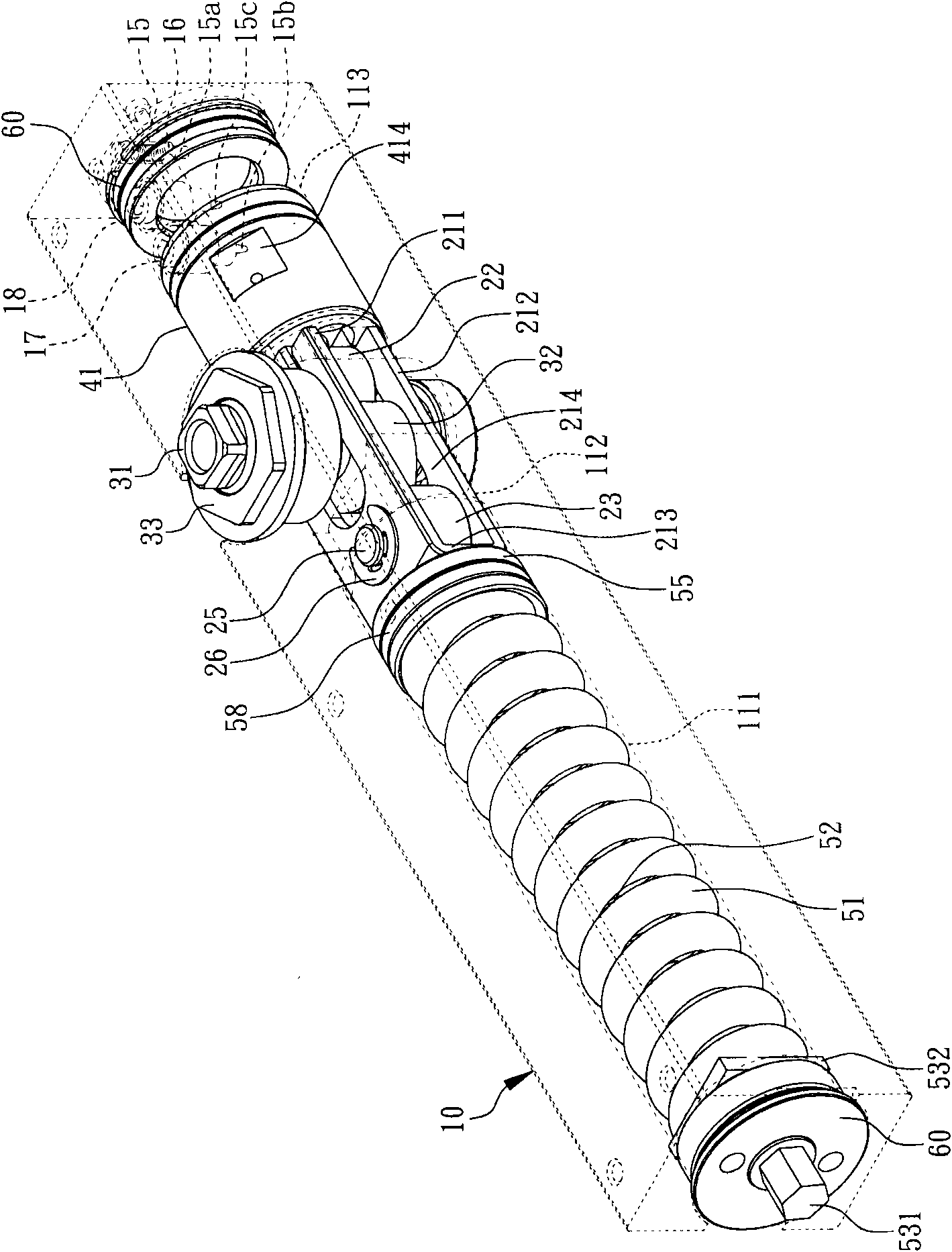
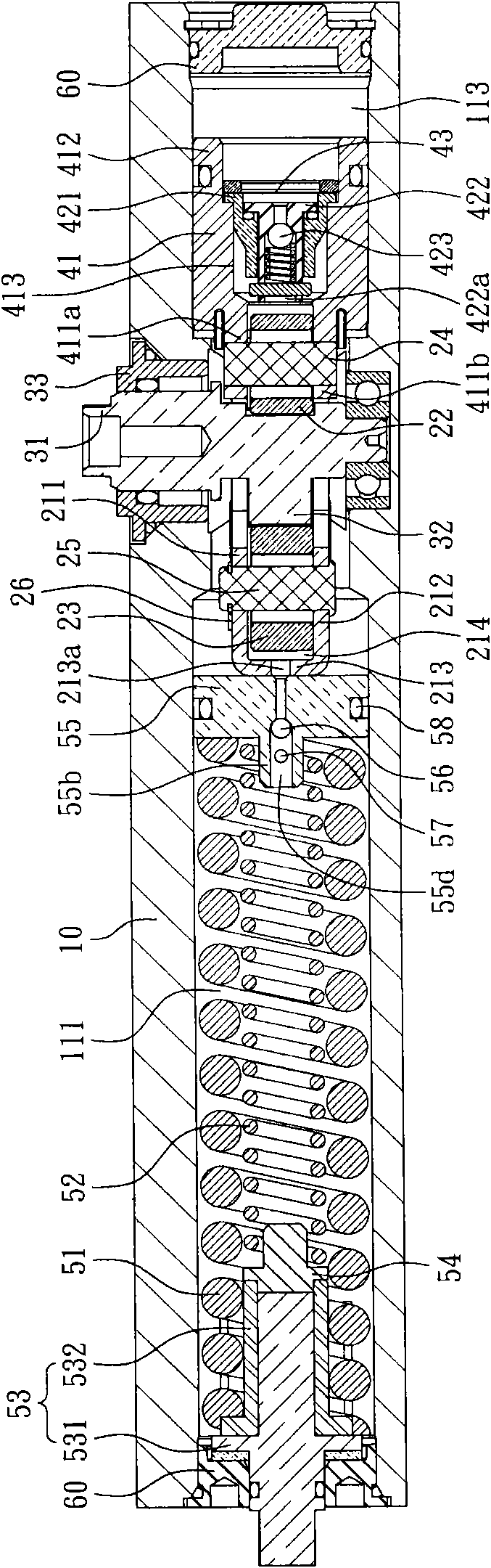
[0067] see figure 1 , figure 2 and image 3 as shown, figure 1 It is an exploded perspective view of a preferred embodiment of the automatic door closer of the present invention, figure 2 It is a three-dimensional view of the combined structure of the preferred embodiment of the automatic door closer of the present invention, image 3 It is a longitudinal sectional view of a preferred embodiment of the automatic door closer of the present invention. The automatic door closer of the preferred embodiment of the present invention includes a housing 10 , a sliding unit 20 , a...


PUM


Abstract

The invention relates to an automatic door closing device, which comprises a shell, a slide unit, a transmission unit, a cylindrical piston and a first elastic part, wherein the shell is provided with a front cavity, a back cavity, an intermediate cavity, a shaft hole passing through the intermediate cavity and a first oil line, and the first oil line is provided with an oil inlet and an oil outlet; the slide unit is arranged on the intermediate cavity and comprises a slide seat and a first roller and a second roller which are arranged in the slide seat; the transmission unit comprises a transmission shaft pivoted in the shaft hole and an eccentric cam which is positioned in the slide seat and is pressed against the first roller and the second roller of the slide unit; the cylindrical piston is arranged in the back cavity and is provided with a first end part and a second end part, and the first end part is connected with the first roller; and the first elastic part is arranged in thefront cavity. The running smoothness of the automatic door closing device can be improved by the reciprocating motion of the slide seat and the cylindrical piston and the action of the first oil line.

Description

technical field [0001] The invention relates to a door closer, in particular to an automatic door closer which utilizes a sliding group and an oil circuit to improve smooth operation. Background technique [0002] The door closer is mainly used to provide a damping effect on the door panel, so that the door panel has a cushioning effect when it is closed, and the elastic element installed inside the door closer can store energy when compressed, so that it can automatically pull slowly when the external force is removed from the door panel The door panel is restored and closed, such as China Taiwan Patent No. 428658, which uses gears, racks and springs to realize the action of the door closer. However, there will be backlash when the gear and the rack of the door closer are meshed. The backlash will increase due to wear and tear, causing intermittent contact between the gear and the rack, causing the door closer to not operate smoothly. [0003] This shows that the above-men...

Claims


Application Information

Patent Timeline
Patent Type & Authority Applications(China)
IPC IPC(8): E05F3/10
Inventor 余勇信
Owner TAIWAN FU HSING INDAL
Why Eureka
Try Eureka