Automatic soil-discharging device for long auger machine

A technology of long helical drilling and automatic rowing, which is applied to drilling tools, drilling equipment, earthwork drilling and production, etc., and can solve problems such as lack of equipment, affecting equipment displacement, and piled up into mountains.

Inactive Publication Date: 2010-01-06
王来朋
View PDF0 Cites 16 Cited by
  • Summary
  • Abstract
  • Description
  • Claims
  • Application Information

AI Technical Summary

Problems solved by technology

[0002] During the foundation construction process of the current long auger drilling machine, a large amount of soil is discharged due to drilling. Because there is no corresponding soil discharge device, the soil is often piled up next to the equipment, which affects the displacement of the equipment.

Method used


Image

  • Automatic soil-discharging device for long auger machine

Examples


Embodiment Construction

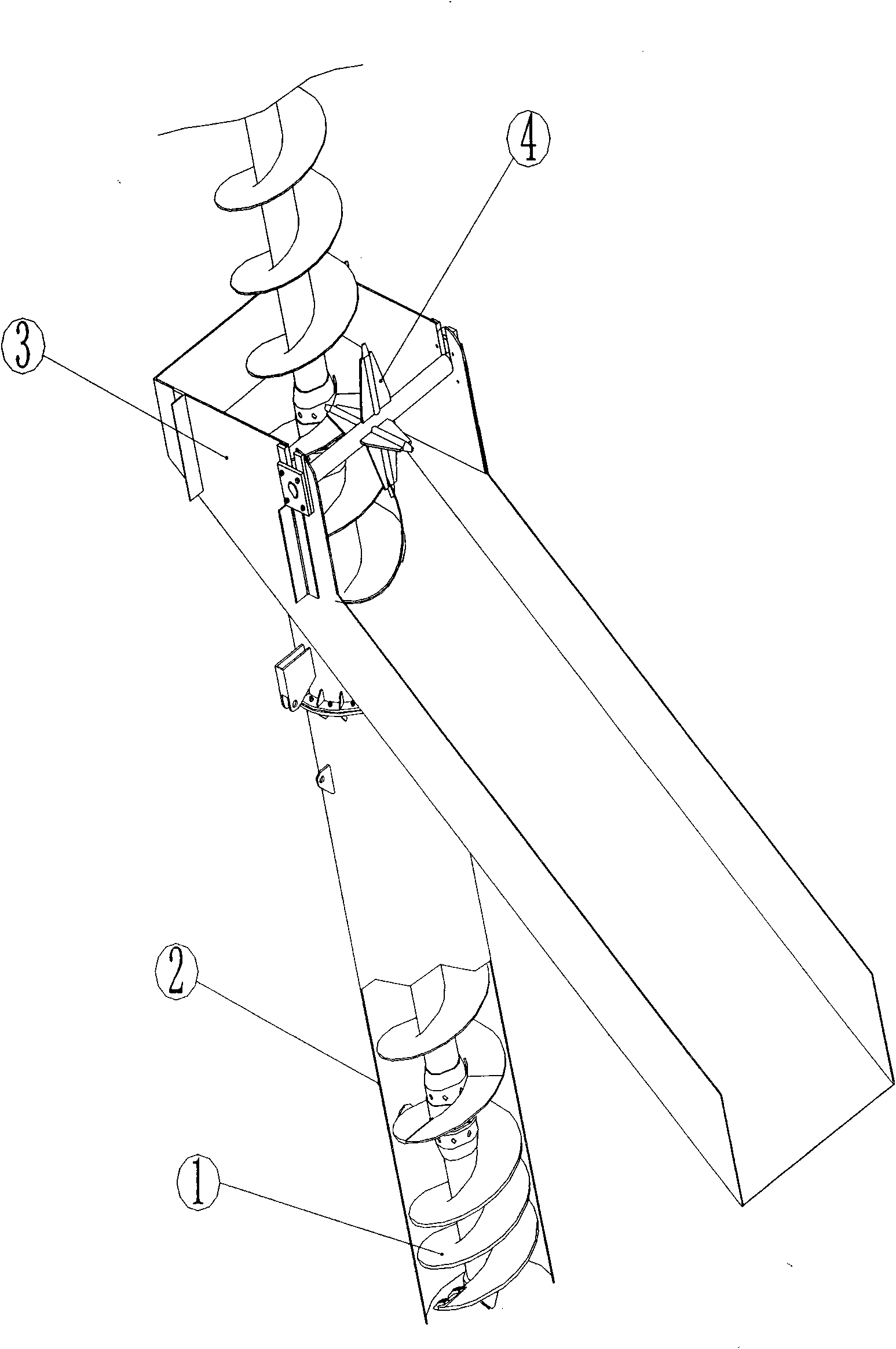
[0006] When the auger rod ① is drilling, the lower part of the excavation guide cylinder ② is inserted into the soil at the orifice. At this time, the soil cut by the drill bit is uploaded along the spiral blades. Under the action of the excavation guide cylinder ②, the soil moves along the inner wall of the cylinder. Rise to the unearthed chute ③, and then slide out along the chute. The transport vehicle can be parked at the exit of the chute to transport the soil directly. Because during the rotary drilling process of the drill pipe, the mud sticks on the drill pipe, and the mud on the blade can be scraped off by the teeth on the soil remover ④. At the same time, the soil remover ④ can follow the rotation under the push of the screw blade.

[0007] The automatic soil dumping device of the long screw drilling machine of the invention can realize the automatic soil dumping of the drill pipe during construction, and facilitate the transportation and external transportation of s...


PUM


Abstract

The invention relates to an automatic soil-discharging device for a long auger machine, which is mainly applied to the long auger machine of pile driving machinery. The automatic soil-discharging device aims to achieve quick excavation and simultaneously discharge soil to a carrier vehicle directly to be transported out of the device. The automatic soil-discharging device mainly comprises a soil-discharging guide cylinder, a soil-discharging chute and a scarification device, wherein the soil drilling rod cut by a drill bit is conveyed upwards along helical blades, and under the action of the soil-discharging guide cylinder (2), the soil is raised to the soil-discharging chute (3) along the inner wall of the cylinder and then slides out along the chute. The automatic soil-discharging device has a simple structure and is practical.

Description

technical field [0001] The invention relates to an automatic soil dumping device of a long screw drilling machine, which is mainly applied to the long screw drilling machine in pile construction machinery and is used for the automatic soil dumping device in the construction process. technical background [0002] In the process of foundation construction, the current long auger drilling machine discharges a large amount of soil due to drilling. Because there is no corresponding soil dumping device, the soil often accumulates into mountains next to the equipment, which affects the displacement of the equipment. SUMMARY OF THE INVENTION [0003] The purpose of the present invention is to realize rapid excavation during construction, and at the same time, the soil is directly discharged onto a transport vehicle to be transported away from the equipment. The invention is mainly composed of excavation guide cylinder, excavation chute and earth remover, and the structure is simpl...

Claims


Application Information

Patent Timeline
Patent Type & Authority Applications(China)
IPC IPC(8): E21B12/06
Inventor 王来朋
Owner 王来朋
Why Eureka
Try Eureka