Rotating magnetic field generator

A technology of rotating magnetic field and generator, which is applied in the direction of variable magnetic field and permanent magnet generated by mechanical movement, which can solve the problems of fast magnetic field attenuation and large gradient of magnetic field strength, and achieve the speed of high rotating magnetic field strength and magnetic field attenuation slow effect

Active Publication Date: 2010-01-20
安吉司润磁性材料股份有限公司
View PDF0 Cites 11 Cited by
  • Summary
  • Abstract
  • Description
  • Claims
  • Application Information

AI Technical Summary

Problems solved by technology

With this structure, such as figure 2 As shown, the attenuation of the magnetic field is fast with the extension o...

Method used


Image

  • Rotating magnetic field generator
  • Rotating magnetic field generator
  • Rotating magnetic field generator

Examples


no. 1 example

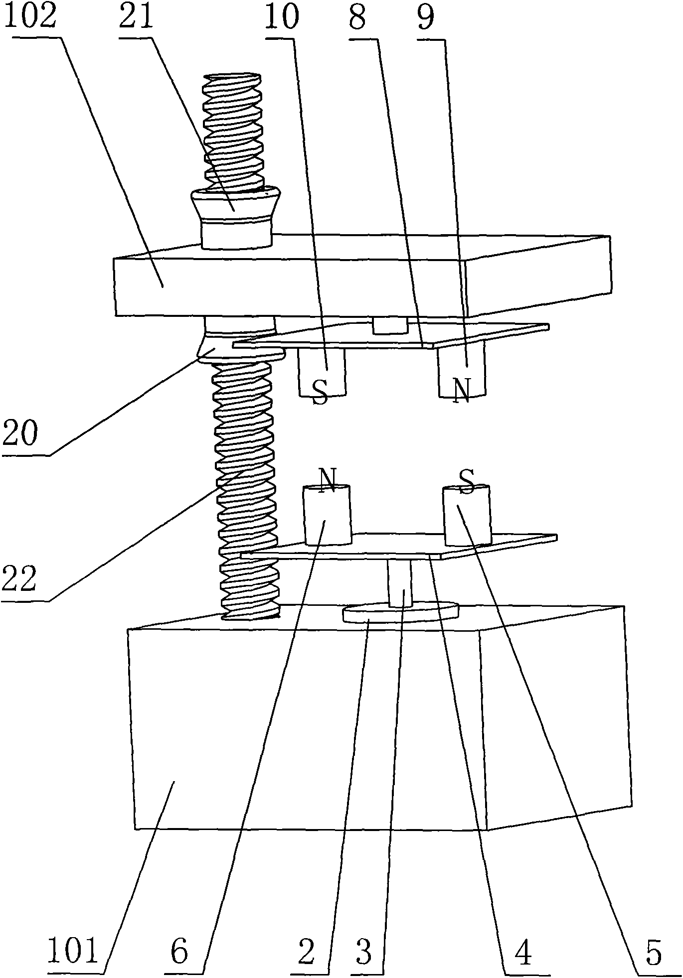
[0019] Such as image 3 The rotating magnetic field generator shown includes a lower bracket 101 and an upper bracket 102, the lower bracket 101 is provided with a motor 2; the output shaft 3 of the motor is provided with a lower soft magnetic turntable 4 made of a soft magnetic material; The soft magnetic turntable 4 is provided with two permanent magnets, i.e. the first permanent magnet 5 and the second permanent magnet 6, the upper end of the first permanent magnet 5 is a south pole, and the upper end of the second permanent magnet 6 is a north pole; The support 102 is provided with an upper soft magnetic turntable 8 made of soft magnetic material; the upper soft magnetic turntable 8 is provided with a rotating shaft 7; the lower surface of the upper soft magnetic turntable 8 is provided with two passive permanent magnets, namely the first passive permanent magnet 9 and the second passive permanent magnet 10, the lower end of the first passive permanent magnet 9 is a north ...

no. 2 example

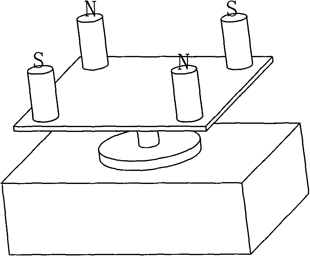
[0022] Such as Figure 4 The rotating magnetic field generator shown includes a lower bracket 101 and an upper bracket 102, the lower bracket 101 is provided with a motor 2; the output shaft 3 of the motor is provided with a lower soft magnetic turntable 4 made of a soft magnetic material; The soft magnetic turntable 4 is provided with four permanent magnets, and the magnetic poles of the adjacent permanent magnets away from the end of the lower turntable are opposite, i.e. two The first permanent magnet 5 and two The second permanent magnet 6, the upper end of the first permanent magnet 5 is a south pole, and the upper end of the second permanent magnet 6 is a north pole; the upper support 102 is provided with an upper soft magnetic turntable 8 made of soft magnetic material; A rotating shaft 7 is provided on the soft magnetic turntable 8; four passive permanent magnets are arranged on the lower surface of the upper soft magnetic turntable 8, namely two The first passive...


PUM


Abstract

The invention discloses a rotating magnetic field generator, comprising a bracket, wherein a motor is arranged on the bracket; a lower turntable is arranged on an output shaft of the motor; even number of permanent magnets are arranged on the lower turntable, and the magnetic poles of the adjacent permanent magnets far away from one end of the lower turntable are opposite; an upper turntable is arranged above the permanent magnets; a rotating shaft is arranged on the upper turntable and is arranged on the bracket; driven permanent magnets with the same number as the permanent magnets of the lower turntable are arranged on the lower surface of the upper turntable, and the permanent magnets correspond to the driven permanent magnets in the vertical direction; the magnetic poles of the driven permanent magnets on the upper turntable far away from one end of the upper turntable are opposite to the magnetic poles of the corresponding permanent magnets of the lower turntable far away from one end of the lower turntable in the vertical direction; and distances between the permanent magnets on the lower turntable and the driven permanent magnets on the upper turntable can be regulated. By utilizing the invention, the attenuation speed of the magnetic field can be decreased, and the strength of the magnetic field is enhanced.

Description

technical field [0001] The invention relates to a magnetic field generator, especially a generator of a rotating magnetic field. Background technique [0002] With the development of science and technology, magnetic field is more and more widely used in medical treatment, health care and daily life, especially the application of rotating magnetic field. Currently, there is a rotating magnetic field generator such as figure 1 As shown, its structure includes a turntable made of soft magnetic material. A permanent magnet is installed on the turntable. The magnetic poles of the adjacent permanent magnets away from the end of the turntable are opposite. A motor is arranged on the turntable. The motor drives the turntable to rotate to form a rotating magnetic field. With this structure, such as figure 2 As shown, with the extension of the space distance used, the decay of the magnetic field is fast; moreover, the magnetic field intensity gradient formed above and below the pe...

Claims


Application Information

Patent Timeline
IPC IPC(8): H01F7/02A61N2/12
Inventor 任柴
Owner 安吉司润磁性材料股份有限公司
Why Eureka
Try Eureka