Bearing device for triaxial adjustment

A bearing device and three-axis technology, applied in the direction of support structure installation, digital processing power distribution, etc., can solve the problems of inconvenient use, inconvenience, and general products without suitable structures, etc., and achieve technological progress, technological innovation, and product structure improvement Effect

Inactive Publication Date: 2011-09-21
THERMALTAKE
View PDF0 Cites 0 Cited by
  • Summary
  • Abstract
  • Description
  • Claims
  • Application Information

AI Technical Summary

Problems solved by technology

[0003] Although the above-mentioned existing conventional fans, lamps or related items can be fixed in the computer case by using the frame and fixing components; It is in a fixed state. Therefore, when it is desired to add other equipment to the computer case, or the fans, lamps or related items need to be adjusted in relevant positions, the fan, lamps or related items must be placed on the frame. Disassemble, and then assemble after the position of the relevant settings is determined, which will cause inconvenience in use; moreover, because the fan, lamp or related items are fixed in position and angle, they cannot be adjusted, so it is relatively difficult to use in actual use. Does not meet the needs of computer mainframe users
[0004] It can be seen that the above-mentioned existing carrying device obviously still has inconvenience and defects in structure and use, and needs to be further improved urgently.
In order to solve the above-mentioned problems, the relevant manufacturers have tried their best to find a solution, but for a long time no suitable design has been developed, and the general product has no suitable structure to solve the above-mentioned problems. This is obviously the relevant industry. Urgent problem

Method used


Image

  • Bearing device for triaxial adjustment
  • Bearing device for triaxial adjustment
  • Bearing device for triaxial adjustment

Examples


Embodiment Construction

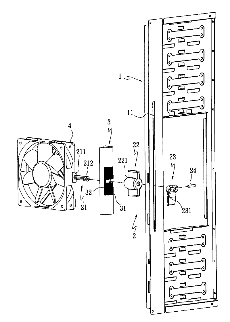
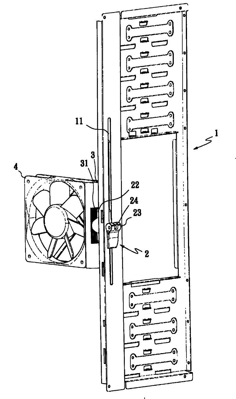
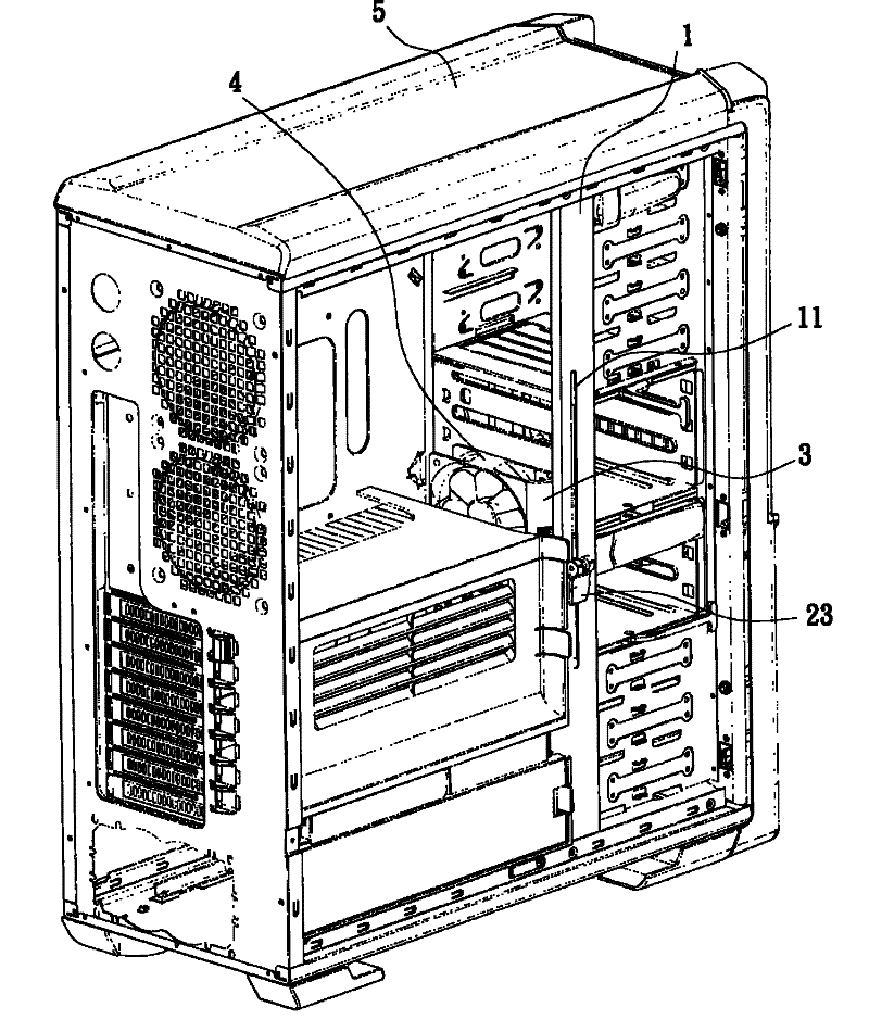
[0036] In order to further explain the technical means and effects of the present invention to achieve the intended purpose of the invention, the specific implementation, structure, and characteristics of the three-axis adjustment bearing device proposed according to the present invention will be described below in conjunction with the accompanying drawings and preferred embodiments. And its effect, detailed description is as follows.

[0037] The aforementioned and other technical contents, features and effects of the present invention will be clearly presented in the following detailed description of preferred embodiments with reference to the drawings. Through the description of the specific implementation mode, when the technical means and functions adopted by the present invention to achieve the predetermined purpose can be obtained a deeper and more specific understanding, but the accompanying drawings are only for reference and description, and are not used to explain th...


PUM


Abstract

The invention relates to a bearing device for triaxial adjustment, which comprises a frame, an adjusting unit, a fixed connecting unit and an actuating unit, wherein the frame is provided with a sliding chute; the adjusting unit is movably combined with the frame; the adjusting unit is provided with a rod body which is movably arranged in the sliding chute and provided with a supporting plate at one end, a pushing piece which is sleeved on the rod body and corresponds to one surface of the sliding chute and a deflector rod which is movably arranged at the other end of the rod body and corresponds to the other side of the sliding chute; the fixed connecting unit is movably combined with the adjusting unit; one surface of the fixed connecting unit is provided with a sawtooth part supported against the pushing piece; the sawtooth part is provided with a slot hole for the rod body to run through; the other surface of the fixed connecting unit is supported against the supporting plate of the rod body; and the actuating unit is arranged in the fixed connecting unit. Therefore, through the cooperation of the frame, the adjusting unit and the fixed connecting unit, the actuating unit can carry out triaxial adjustment of the movement in vertical direction and the rotation in horizontal direction and vertical direction on the frame.

Description

technical field [0001] The invention relates to a three-axis adjustable bearing device, in particular to a frame, an adjustment unit and a fixed unit that can be used to cooperate to make the action unit move vertically, rotate horizontally and rotate vertically on the frame Three-axis adjustment of the bearing device. Background technique [0002] Generally, when fans, lamps, or related required items are set in the existing computer casings, they are usually assembled with the cooperation of the required frame and fixing components; in order to achieve the required use of being fixed in the computer casing action. [0003] Although the above-mentioned existing conventional fans, lamps or related items can be fixed in the computer case by using the frame and fixing components; It is in a fixed state. Therefore, when it is desired to add other equipment to the computer case, or the fans, lamps or related items need to be adjusted in relevant positions, the fan, lamps or re...

Claims


Application Information

Patent Timeline
Patent Type & Authority Patents(China)
IPC IPC(8): H05K7/14G06F1/18
Inventor 林培熙
Owner THERMALTAKE
Why Eureka
Try Eureka