Packaging method for combining screw to printed circuit board

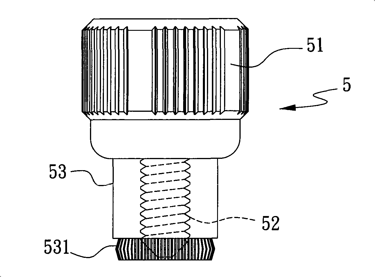
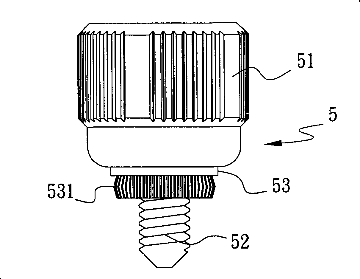
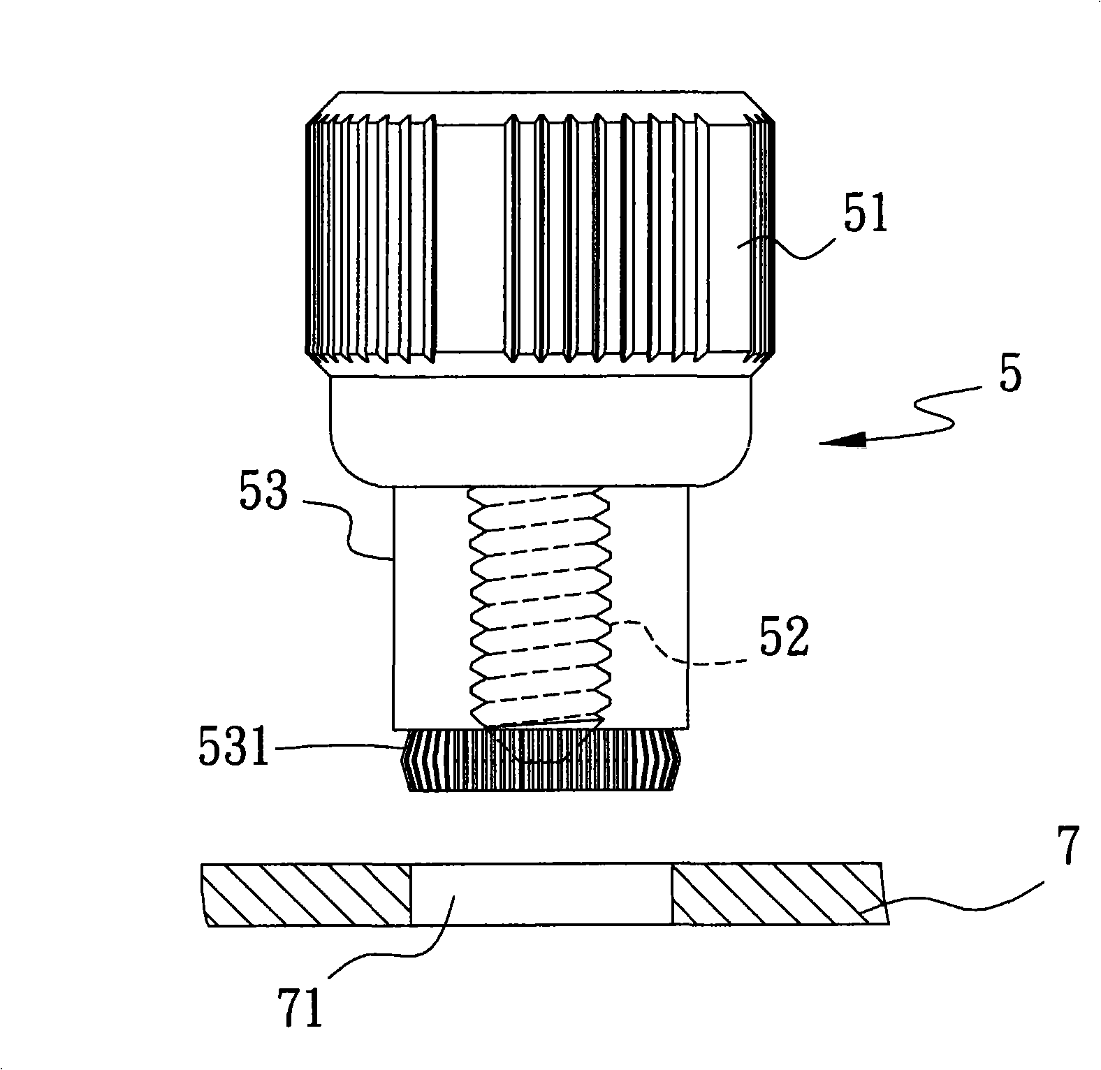
A technology of printed circuit board and packaging method, which is applied in the directions of printed circuit, printed circuit manufacturing, printed circuit connected with non-printed electrical components, etc., can solve the problem of skew, small screw 5, and inability of screw head 51 and sleeve 53 to compress Fixed issues

Active Publication Date: 2009-08-26
DTECH PRECISION INDS
View PDF0 Cites 1 Cited by
  • Summary
  • Abstract
  • Description
  • Claims
  • Application Information

AI Technical Summary

Problems solved by technology

[0003] Although the above-mentioned prior known packaging method of combining screws with printed circuit boards can combine the screws 5 into the through holes 71 of the printed circuit board 7, when the screws 5 are set, their sleeves 53 directly correspond to the through holes 71, which The screw head 51 and the sleeve 53 cannot be compressed and fixed, so it needs to be placed manually, and the volume of the used screw 5 and the aperture of the perforation 71 are small. Therefore, when the flange 531 of the screw 5 sleeve 53 is to be arranged on the When perforating the hole 71, it is easy to cause errors during manual placement, so that the flange 531 of the sleeve 53 cannot be aligned with the perforation 71 smoothly, resulting in poor pressing of the printed circuit board and causing damage to the board, and when the flange 531 of the sleeve 53 cannot When it is installed in the through hole 71 once, the flange 531 of the sleeve 53 cannot be completely pressed

Method used


Image

  • Packaging method for combining screw to printed circuit board
  • Packaging method for combining screw to printed circuit board
  • Packaging method for combining screw to printed circuit board

Examples


Embodiment Construction

[0036] In order to further explain the technical means and effects that the invention takes to achieve the intended purpose of the invention, the specific implementation, structure, Features and their functions are described in detail below.

[0037] The aforementioned and other technical contents, features and effects of the invention will be clearly presented in the following detailed description of preferred embodiments with reference to the drawings. Through the description of the specific implementation, one can get a deeper and more specific understanding of the technical means and effects of the invention to achieve the intended purpose. However, the attached drawings are only for reference and description, not for the purpose of the invention. be restricted.

[0038] see Figure 6 Shown is the flow chart of the packaging method of the present invention that combines screws with printed circuit boards, and please refer to Figure 7 to Figure 11 as shown, Figure 7is...


PUM


Abstract

The invention relates to a packaging method for combining a screw to a printed circuit board, which is a method for combining the screw to the printed circuit board by a surface adhesion technique and comprises the following steps: providing a screw having a screw head, a screw rod extending out of one end of the screw head, and a sleeve sleeved on the periphery of the screw rod and movably arranged on one end face of the screw head; sleeving a limit ring on the screw rod to lean against one end of the sleeve so that part of the sleeve is limited in the screw head; arranging an adhesive layer on the other end face of the screw head; providing the printed circuit board with a plurality of through holes and arranging a soldering tin layer; making a tool use the screw through the adhesive layer and moving the tool so that the screw rod corresponds to the through holes; making the tool release the screw to drop the screw, and arranging a flange of the sleeve in the through holes; heating the soldering tin layer to melt tin, and cooling the soldering tin layer to the normal temperature so as to harden the soldering tin layer; fixedly arranging the sleeve in the through holes; and removing the limit ring. The method has the efficacy of achieving precise, non-offset, non-deflective and easy arrangement in the process of arranging a screw sleeve.

Description

technical field [0001] The invention relates to a packaging method for combining screws with a printed circuit board, in particular to a packaging method for combining screws with a printed circuit board, which can achieve the functions of precision, no deviation, no skew and easy setting when setting the screw sleeve method. Background technique [0002] see Figure 1 to Figure 5 as shown, figure 1 It is the structural representation of the existing screw Figure 1 , figure 2 is a structural representation Figure II , image 3 It is a schematic illustration of the conventional packaging method of combining screws with printed circuit boards Figure 1 , Figure 4 is a gesture Figure II , Figure 5 is a gesture Figure three . Generally, the existing customary method of combining screws on a printed circuit board is to use a screw 5 with a screw head 51, a screw rod 52 and a sleeve 53 to correspond to the perforation of a printed circuit board 7 with the sleeve ...

Claims


Application Information

Patent Timeline
IPC IPC(8): H05K1/18H05K3/00
Inventor 王鼎瑞吴明德
Owner DTECH PRECISION INDS
Why Eureka
Try Eureka