Locking mechanism of miniature electric connector

A technology of locking mechanism and electrical connector, which is applied in the direction of connection, parts and circuits of connecting devices, etc., which can solve problems such as inability to fit in place and limit the application of locking mechanism

Inactive Publication Date: 2010-01-27
GUIZHOU SPACE APPLIANCE CO LTD
View PDF0 Cites 5 Cited by
  • Summary
  • Abstract
  • Description
  • Claims
  • Application Information

AI Technical Summary

Problems solved by technology

In addition, due to the limitation of the structure of the retaining ring and the locking screw, the locking screw can only be screwed into the threaded part when engaging

Method used


Image

  • Locking mechanism of miniature electric connector
  • Locking mechanism of miniature electric connector
  • Locking mechanism of miniature electric connector

Examples


Embodiment Construction

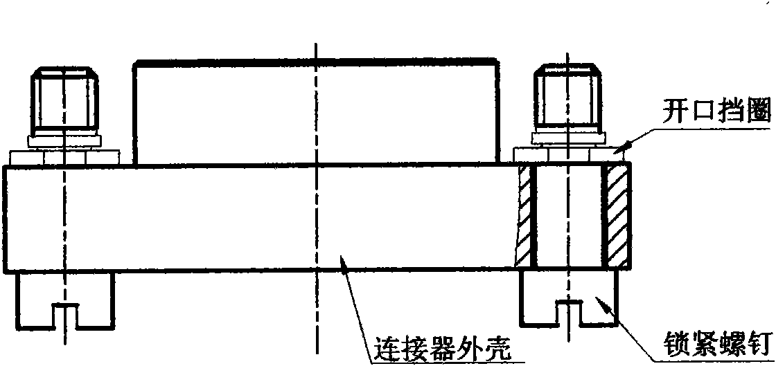
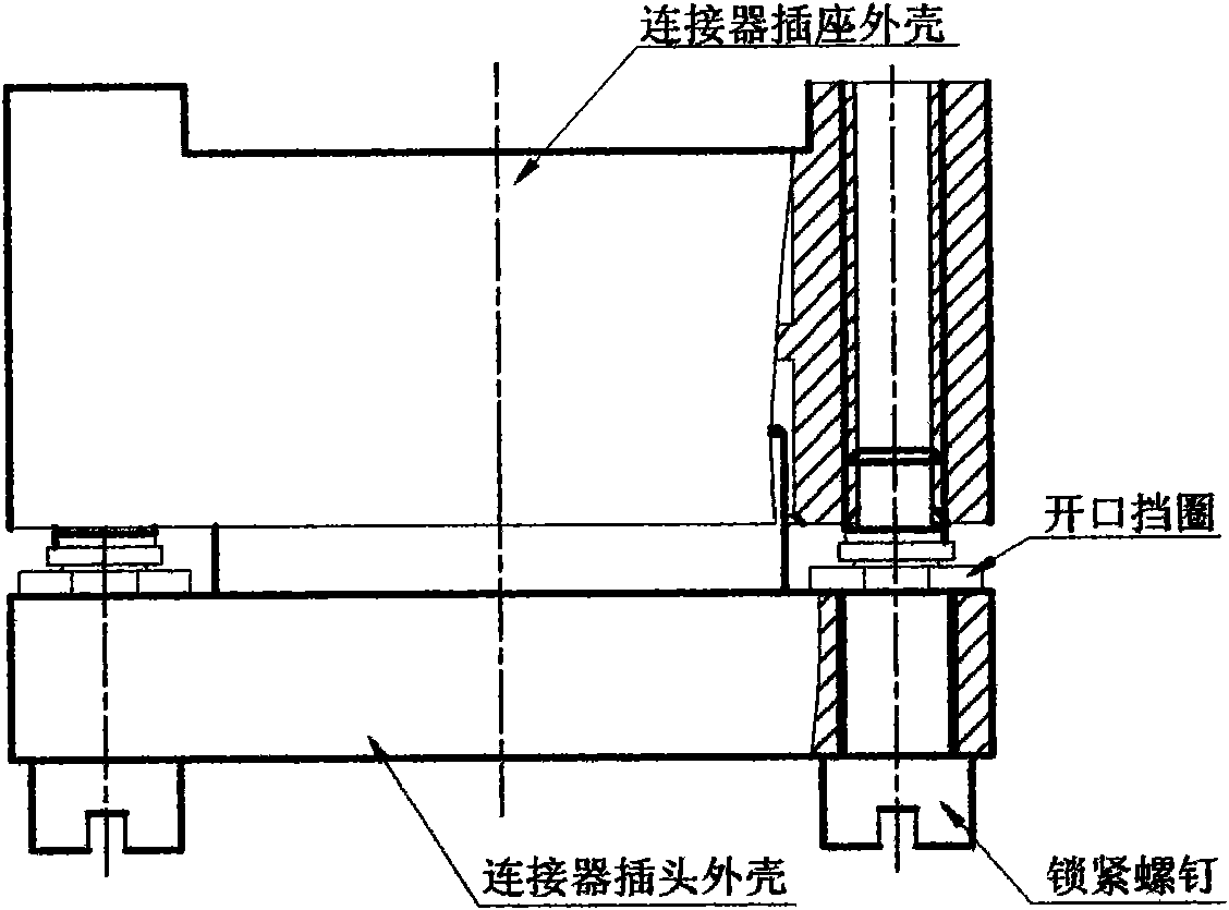
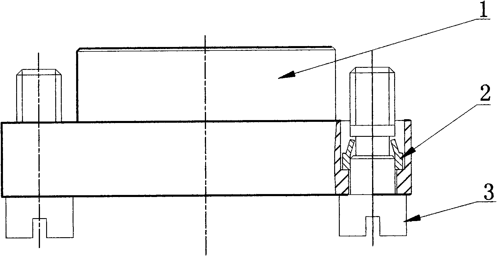
[0010] As shown in the figure, the locking mechanism of the electrical connector of the present invention is composed of a shrinking sleeve 2 and a locking screw 3. The locking screw 3 is provided with an annular groove 4, and one end of the transition between the annular groove 4 and the upper and lower sections is Chamfering, the other end is a right angle, the chamfering structure ensures that the sleeve can be easily put in place, and the right angle structure ensures that the sleeve can reliably block the shrinking sleeve after shrinking. The necking sleeve 2 has a stepped structure, and the strength of the thin-walled part is relatively low. The shrinking can be realized by pressing it with a tapered sleeve. The shrinking sleeve is stuck in the annular groove of the locking screw so that the lock Tighten the screws to fix it on the case. There is a certain gap between the casing, the locking screw and the matching surface of the casing, and there is also a certain gap be...


PUM


Abstract

The invention relates to a locking mechanism of a miniature electric connector. The locking mechanism comprises a necking sleeve and a locking screw which is provided with a circular groove; a chamfer angle is arranged at one end of the circular groove, and a taper angle is arranged at the other end; the necking sleeve is in a step structure and comprises a conical thin wall part and a round thick wall part; the conical thin wall part is mounted in the circular groove of the locking screw and in a step fixed hole corresponding to an outer shell of the electric connector; and the abutting part of the locking screw, which is exposed out of the outer shell of the electric connector, is a full thread. The locking mechanism of the miniature electric connector occupies small space, can obtain a smaller center distance of the electric connector, be beneficial to the miniaturized development and realize the seamless attachment of a plug and a socket outer shell after being spliced.

Description

technical field [0001] The invention relates to a locking mechanism of an electrical connector, which belongs to the technical field of electrical connectors. Background technique [0002] The locking screws of common miniature electrical connectors are generally fixed on the connector shell by an open retaining ring. The typical structure is as follows: figure 1 shown. The open retaining ring is clamped in the annular groove of the locking screw, thereby restricting the locking screw from detaching from the shell. The open retaining ring of this structure must fit on the shell plane, and the position of the retaining ring must be cleared when the connector plug and socket are docked. Therefore, the connector with the open retaining ring structure generally has a relatively large center distance of the locking screw. In addition, due to the limitation of the structure of the retaining ring and the locking screw, the locking screw can only be screwed into the threaded part ...

Claims


Application Information

Patent Timeline
IPC IPC(8): H01R13/621
Inventor 陈晓文
Owner GUIZHOU SPACE APPLIANCE CO LTD
Why Eureka
Try Eureka