

Flexible printed circuit board
A flexible printing and circuit board technology, which is applied in the direction of printed circuit components, electrical connection printed components, etc., can solve the problems of difficult control of insertion depth, inaccurate or offset, large tolerance of silk screen alignment line, etc., to improve FPC Reliable performance of electrical contact, avoiding misalignment or offset, and improving the effect of plugging positioning accuracy
- Summary
- Abstract
- Description
- Claims
- Application Information
AI Technical Summary
Problems solved by technology
Method used
Image

Examples
Embodiment 1
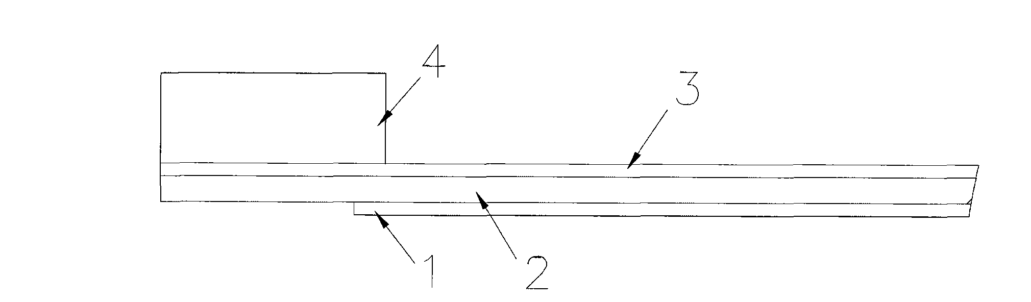
[0054] FIG. 2( a ) is a schematic diagram of the back structure of a flexible printed circuit board according to an embodiment of the present invention. Fig. 2(b) is a schematic diagram of the structure in direction B in Fig. 2(a). see Figure 2(a) ~ Figure 2(b) , the FPC includes: an insulating cover film layer 1, a conductive copper foil 2, an insulating base material 3 and a first reinforcing plate 4, and the insulating cover film layer 1 and the conductive copper foil 2, and the conductive copper foil 2 and the insulating base are respectively connected by an adhesive. Material 3, insulating base material 3 and first reinforcing plate 4.
[0055] The material of the insulating cover film layer 1 is high temperature resistant, high-strength flexible polymer material polyimide, and the end of the insulating cover film layer 1 facing the FPC insertion direction is slotted, so that one end of the conductive copper foil 2 is exposed to the insulating cover Outside the film lay...
Embodiment 2
[0065] FIG. 3( a ) is a schematic diagram of the back structure of the flexible printed circuit board according to Embodiment 2 of the present invention, and FIG. 3( b ) is a schematic diagram of the structure along the direction C in FIG. 3( a ). see Figure 3(a) ~ Figure 3(b) ,and Figure 2(a) ~ Figure 2(b) The difference is that the FPC also includes: the first reinforcing film 5,
[0066] Connect the insulating base material 3 and the first reinforcing plate 4 through the first reinforcing film 5, between the first reinforcing film 5 and the insulating base material 3, and between the first reinforcing film 5 and the first reinforcing plate 4 Glued together with adhesive.
[0067] The thickness of the first reinforcing film 5 can be 0.008-0.025 mm. Along the FPC insertion direction, the first reinforcing film 5 is about 1-3 mm longer than the first reinforcing plate 4, that is, one end of the first reinforcing film 5 It is flush with the insertion surface of the first re...
Embodiment 3
[0075] FIG. 4( a ) is a schematic diagram of the back structure of the flexible printed circuit board according to Embodiment 3 of the present invention, and FIG. 4( b ) is a schematic diagram of the structure in the direction D of FIG. 4( a ). see Figure 4(a) ~ Figure 4(b) ,and Figure 2(a) ~ Figure 2(b) The difference is that the FPC also includes: a second reinforcing plate 8,
[0076] The second reinforcing plate 8 is bonded to the insulating base material 3 through an adhesive;
[0077] The thickness of the second reinforcing plate 8 is the same as that of the first reinforcing plate 4, and the length is about 1-5 mm. There is 0.2-0.5 mm between the second reinforcing plate 8 and the first reinforcing plate 4 in the direction of FPC insertion. The insulating substrate transition region 10 serves as a connection. Similar to the above, the insulating substrate transition region 10 with a length of 0.2-0.5 mm is only a preferred choice in this embodiment.
[0078] Due to...
PUM
| Property | Measurement | Unit |
|---|---|---|
| Length | aaaaa | aaaaa |
Abstract
Description
Claims
Application Information