Communication system, management apparatus, communication apparatus and computer program

A communication system and communication device technology, applied in the direction of transmission system, synchronization device, digital transmission system, etc., can solve the problems of not considering the deviation of the internal clock time itself, the difference of the set time, etc.

Inactive Publication Date: 2010-01-27
MITSUBISHI ELECTRIC CORP
View PDF1 Cites 14 Cited by
  • Summary
  • Abstract
  • Description
  • Claims
  • Application Information

AI Technical Summary

Problems solved by technology

[0007] Regarding the time synchronization protocols in NTP and IEEE 1588, it is assumed that requests and responses are sent in reverse on the same path. If the paths of requests and responses are different, such as in a ring network, correct time synchronization cannot be performed.
[0008] In addition, in the method of simply transmitting the time and only aligning with the time aligned with the time, due to the influence of transmission delay, relay delay, etc., depending on the position of the node device in the ring, there will be an error at the set time. difference
[0009] In addition, in the method of synchronizing processes in a ring network such as Patent Document 1, the scheduled synchronization time is obtained in consideration of delay, but the deviation of the time itself of the internal clock of each node device is not considered.

Method used


Image

  • Communication system, management apparatus, communication apparatus and computer program
  • Communication system, management apparatus, communication apparatus and computer program
  • Communication system, management apparatus, communication apparatus and computer program

Examples


Embodiment approach 1

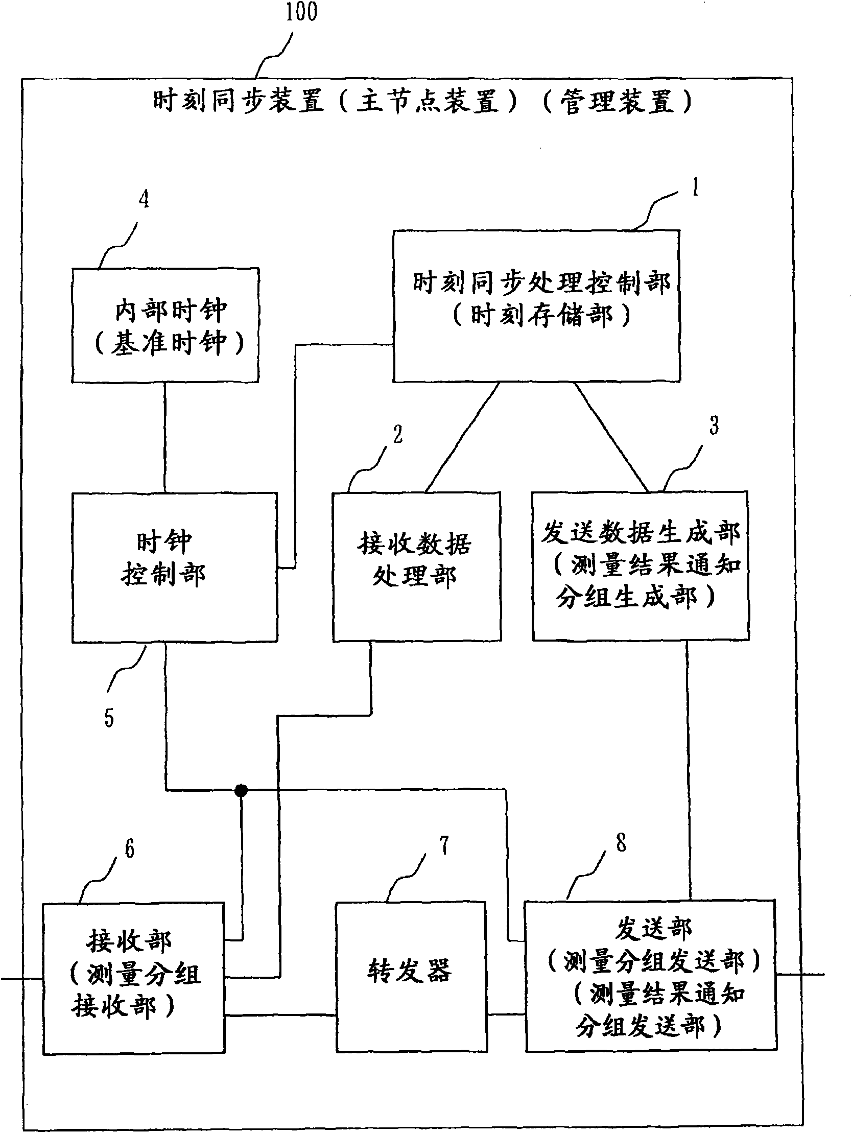
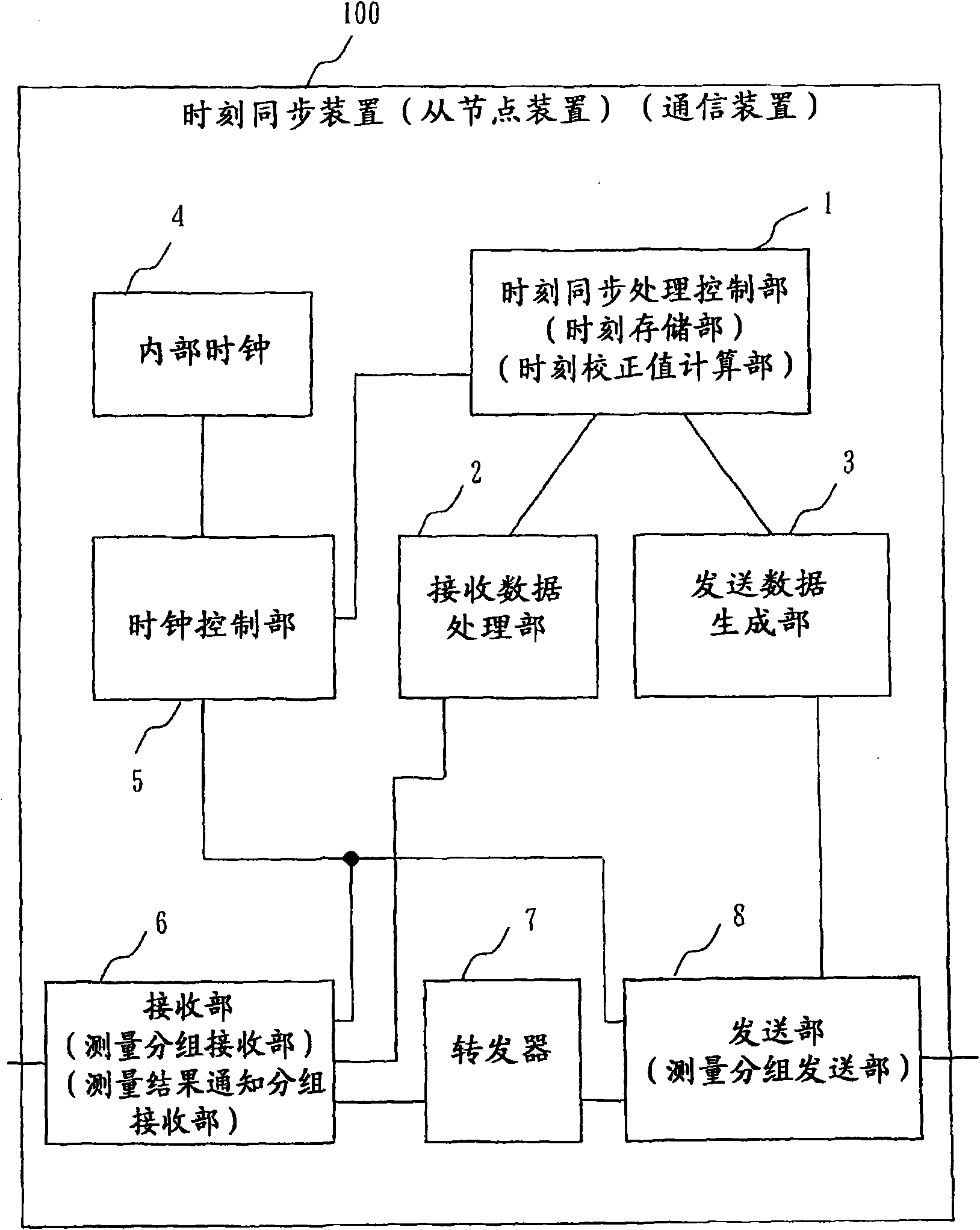
[0139] figure 1 as well as figure 2 It is a figure which shows the structural example of the time synchronization apparatus 100 of this embodiment.

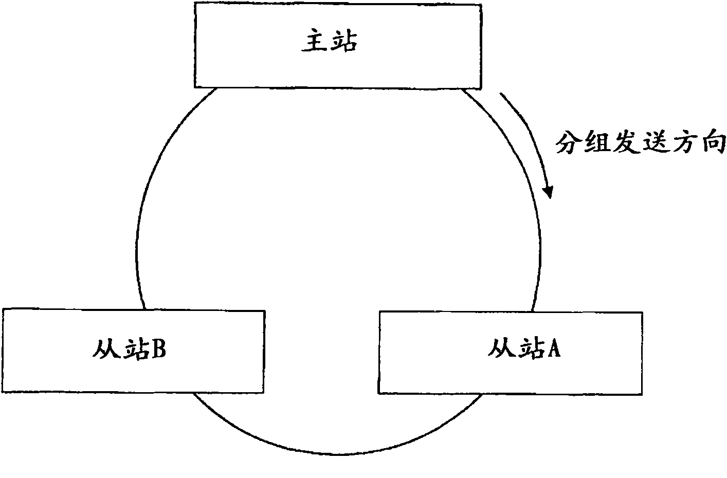
[0140] In this embodiment, multiple time synchronization devices 100 such as image 3 shown are connected to form a ring network.

[0141] That is, the target communication system in this embodiment is as follows image 3 Shown is a ring network in which a master node device serving as a management device and a plurality of slave node devices serving as communication devices are ring-connected. The master node device and the slave node device are each a time synchronization device 100 .

[0142] Packets transmitted from each node device such as image 3 Shown always teleports in a fixed direction. Such constraints are not limited to hardware constraints, but also occur when time-synchronized control is performed in an upper layer that does not have a unit for controlling the transmission direction.

[0143] Additionally, ...

Embodiment approach 2

[0281] In Embodiment 1 above, the time correction value was calculated from the measured value including the relay processing time in the slave station, but next, it will be shown that each slave station measures the reception time and transmission time, and uses This is a time synchronization method for calculating the time correction value by relaying the measurement value of the processing time in the station.

[0282] Figure 13 is a diagram showing a packet switching procedure in such a case.

[0283] In this embodiment, the master station and the slave station respectively extract the reception time and transmission time of the measurement packet, and subtract the total of the relay processing time in all slave stations, that is, the total delay time of each slave station, from the actual measurement value of the delay time when the packet makes a circle. The sum of the difference between the received time and the sent time of the measured packet in the station, the sum...


PUM


Abstract

In a ring type network, a master node transmits a determination packet to a slave node; receives the determination packet having taken a round of a plurality of slave nodes; stores determination packet transmission and reception times in accordance with the timings of an internal clock; and transmits a transmission result notifying packet, which is indicative of the determination packet transmission and reception times, to the slave node. Each of the slave nodes receives the determination packet; transmits the received determination packet to a next node; stores a determination packet reception time in accordance with the timing of an internal clock; also receives the transmission result notifying packet; calculates a time correction value by using the determination packet transmission and reception times indicated by the received transmission result notifying packet, the stored determination packet reception time, the total number of the node apparatuses and using a difference in packet transfer order between that slave node and the master node; and corrects the time of the internal clock by using the calculated time correction value.

Description

technical field [0001] The present invention relates to time synchronization technology among a plurality of node devices connected to a ring network, for example. Background technique [0002] Conventional time synchronization protocols include NTP (Network Time Protocol) and IEEE 1588. [0003] Also, as a method of aligning time in a ring network, a method of simply transmitting the time of a reference node device and aligning with the time is conceivable. [0004] In addition, a method of synchronizing processes in a ring network has also been proposed (for example, Patent Document 1). [0005] Patent Document 1: Japanese Patent Laid-Open No. 2002-247059 [0006] The problem to be solved by the invention [0007] As for the time synchronization protocols in NTP and IEEE 1588, it is assumed that requests and responses are sent in reverse on the same path. If the paths of requests and responses are different like in a ring network, accurate time synchronization cannot be...

Claims


Application Information

Patent Timeline
Patent Type & Authority Applications(China)
IPC IPC(8): H04L12/42H04L7/00
CPCH04J3/0667H04L12/422H04J3/0664
Inventor 樱田博三部健
Owner MITSUBISHI ELECTRIC CORP
Why Eureka
Try Eureka