Anti-theft lockset

A lock and lock body technology, which is used in construction locks, cylinder pin locks, locks with turning keys, etc., can solve the problems of good anti-theft performance, and locks are easily damaged by force, so as to achieve good anti-theft performance and prevent thieves from destroying the lock. Effect

Inactive Publication Date: 2013-01-09
吴潮胜
View PDF0 Cites 0 Cited by
  • Summary
  • Abstract
  • Description
  • Claims
  • Application Information

AI Technical Summary

Problems solved by technology

[0003] The technical problem to be solved by the present invention is to provide an anti-theft lock, which can solve the problem that the lock is easily destroyed by force, and has good anti-theft performance

Method used


Image

  • Anti-theft lockset
  • Anti-theft lockset
  • Anti-theft lockset

Examples


Embodiment 1

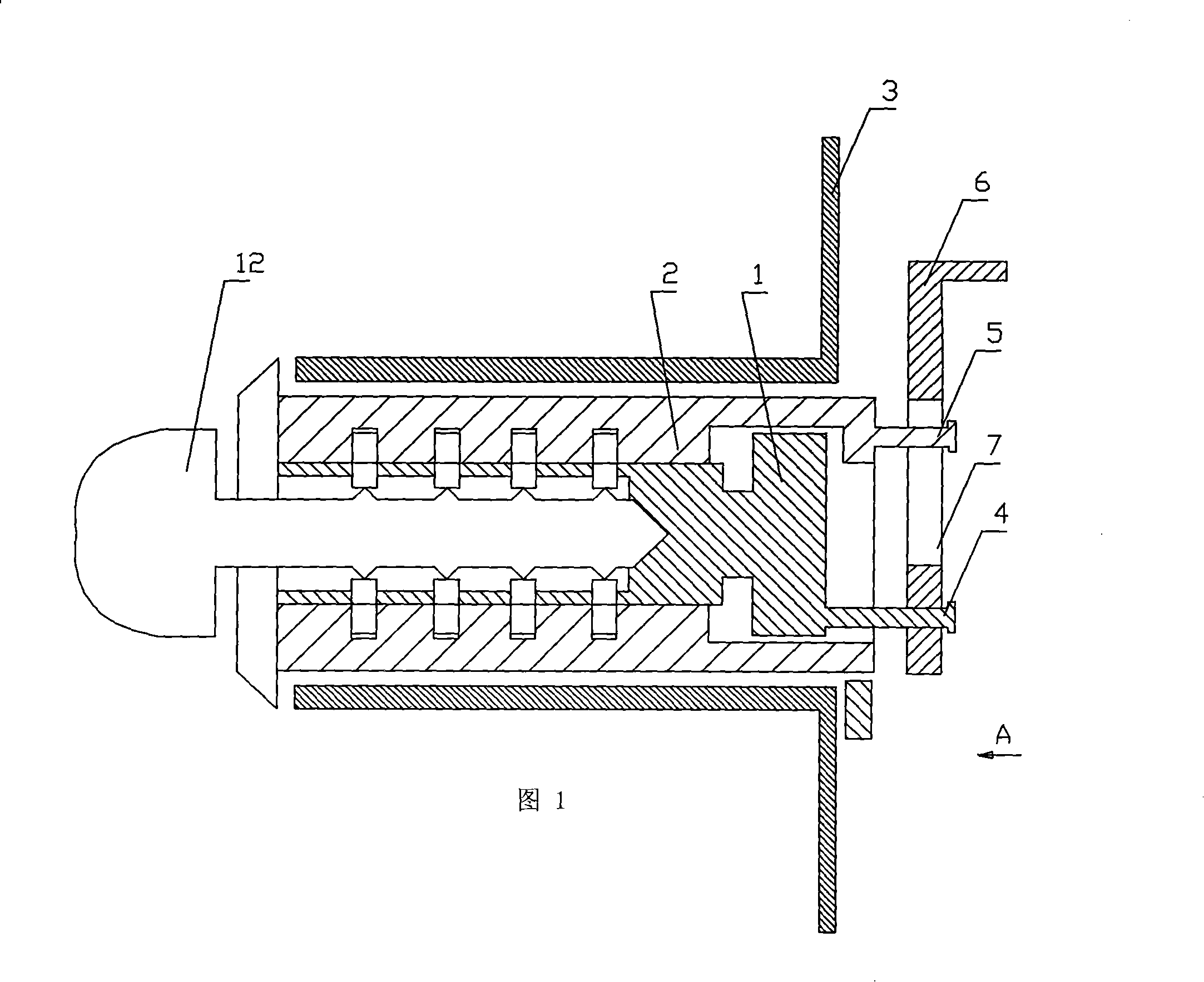
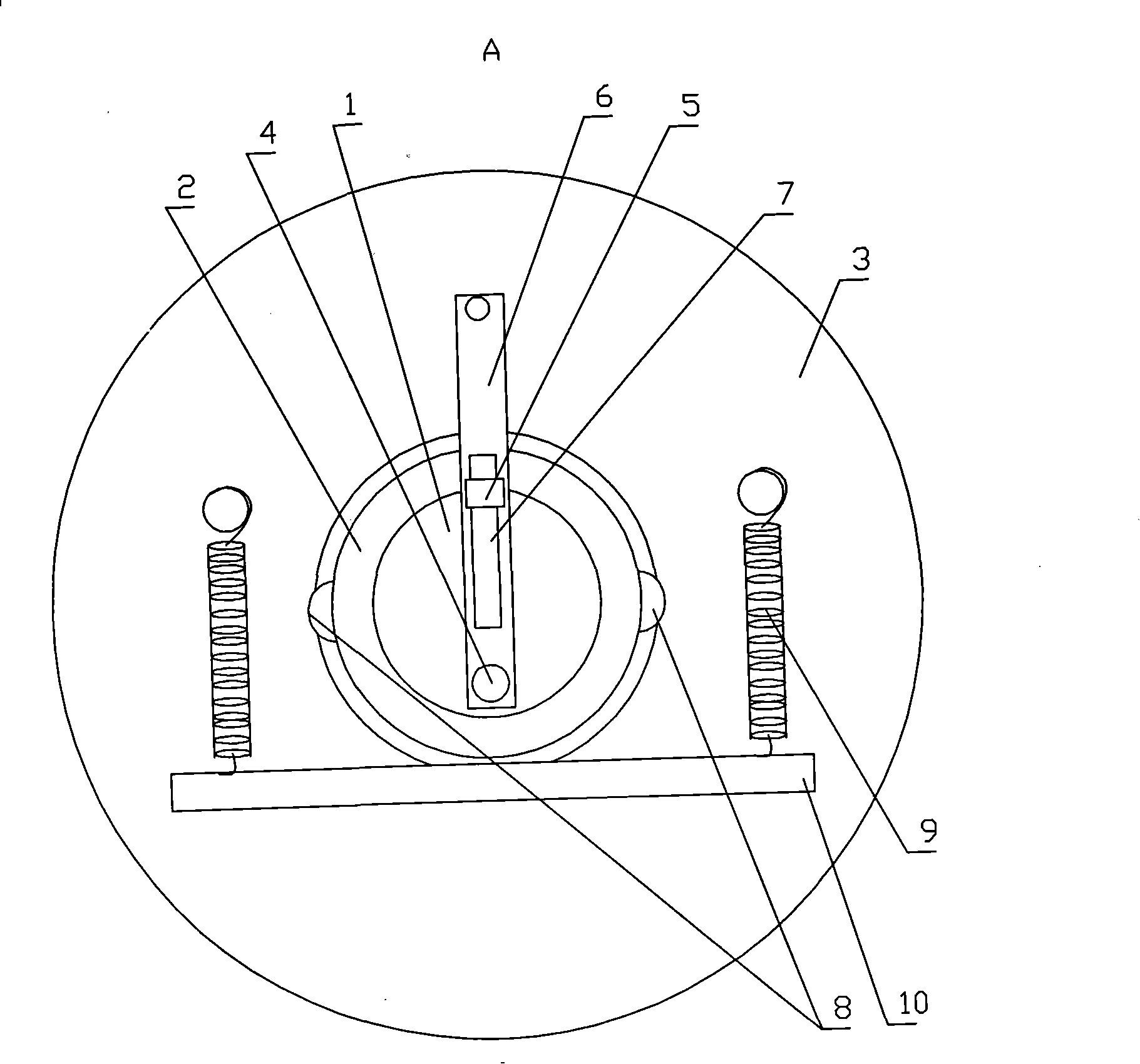
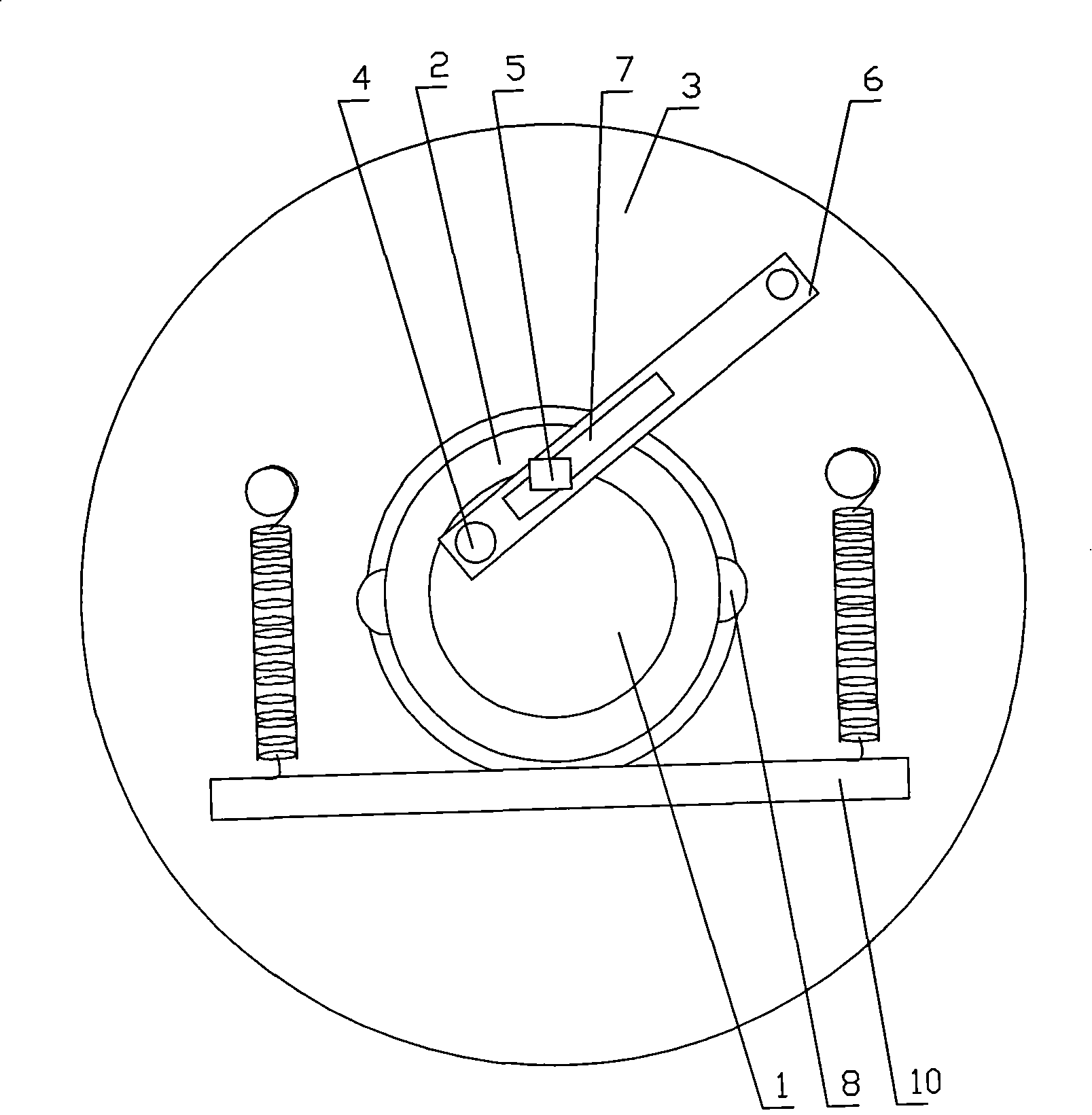
[0018] Embodiment 1: as Figure 1 to Figure 3 As shown, the anti-theft lockset includes a lock core 1, a lock body 2, and a locking mechanism that limits the relative movement of the lock core 1 and the lock body 2. Like a commonly used locking mechanism, the locking mechanism is arranged on the lock core 1 and the lock body 2. It consists of a plurality of sliding holes, a plurality of sliding columns and a return spring, and the lock cylinder is located in the lock body. The internal structure of lock cylinder, lock body is the same with most existing locksets. The lock body 2 is cylindrical, the axes of the lock body 2 and the lock cylinder 1 are the same, the lock body 2 is located in the lock body hole of the shell 3, and the lock body 2 can rotate 360 ​​degrees relative to the shell. A positioning shaft 4 is provided on the distal end surface of the lock core 1 away from the key hole, and the positioning shaft 4 is arranged near the periphery of the distal end surface o...

Embodiment 2

[0020] Embodiment 2: It also includes a movable lock bolt 11, and the lock bolt 11 is provided with bar-shaped teeth; the lock cylinder is inserted with a matching key, and after the lock cylinder and the lock body are rotated in corresponding phases, the bar is pulled to touch the lock on the lock bolt. bar teeth. After the lock core rotates relative to the lock body, the distance between the end of the pulling bar that is far away from the positioning shaft and the axis of the lock core changes, and the distance becomes larger. There is a certain distance between the position and the sliding hole, and the lock cylinder and the lock body cannot produce relative movement in the radial direction, so that the positioning shaft cannot pass over the positioning column, the lock cylinder can no longer rotate relative to the lock body, and the lock cylinder and the lock body rotate at the same time. The deadbolt mechanism can be touched or pulled, at which point the lock can be open...


PUM


Abstract

The invention discloses an anti-theft lockset, which comprises a lock cylinder, a lock body and a locking mechanism for restricting the relative movement of the lock cylinder and the lock body, wherein the lock cylinder is positioned in the lock body. The anti-theft lockset is characterized in that the lock body is in a cylindrical shape; the lock body and the lock cylinder have the same axis; the lock body is positioned in a lock body hole of a shell and can rotate 360 degrees relative to the shell; the end face of the far end of the lock cylinder away from a keyhole is provided with a positioning axle which is arranged near the periphery of the end face of the far end of the lock cylinder away from the keyhole; the lock body is provided with a positioning column on the end face of the far end of the lock body away from the keyhole; a toggle bar is positioned near the end face of the far end of the lock cylinder away from the keyhole; an elongated sliding hole is arranged near the middle part of the toggle bar; one end of the toggle bar is rotatably connected with the positioning axle; the positioning column is positioned in the sliding hole and can slide along the sliding hole; and a resistance structure which resists the lock body when the lock body rotates to a certain phase is also arranged on the ant-theft lockset. The anti-theft lockset has a simple structure, can prevent the lock from being unlocked by violence, and has good anti-theft performance.

Description

technical field [0001] The invention relates to an anti-theft lockset. Background technique [0002] Locksets in the prior art are all composed of a lock core and a lock body. The lock core is located in the lock body. A locking mechanism is provided between the lock core and the lock body. The locking mechanism limits the relative movement between the lock core and the lock body. Locking mechanism has many structures, and commonly used locking structure is all made of a plurality of sliding holes, a plurality of sliding posts, and return springs arranged on the lock cylinder and the lock body. Insert a suitable key into the key hole of the lock cylinder. After the teeth on the key push the sliding column of the locking mechanism, the lock cylinder can move relative to the lock body with the key. After the lock cylinder can move, other locks connected to the lock cylinder can be opened. Bolt mechanism so that the lock can be opened. But there is such defect in this kind of...

Claims


Application Information

Patent Timeline
Patent Type & Authority Patents(China)
IPC IPC(8): E05B27/10E05B19/00
Inventor 吴潮胜
Owner 吴潮胜
Why Eureka
Try Eureka