Method and device for ray bundle scanning for back scattering imaging

A technology of scanning device and scanning method, applied in the field of ray beam scanning method and device

Inactive Publication Date: 2010-02-10
NUCTECH CO LTD +1
View PDF1 Cites 25 Cited by
  • Summary
  • Abstract
  • Description
  • Claims
  • Application Information

AI Technical Summary

Problems solved by technology

However, every time the rotating flywheel rotates one revolution, each position of the radial groove on it (except the intersection point where the radial groove and the linear groove on the vertical collimator perpendicularly intersect) will be used twice to form a scanning collimation hole, This requires that each position of the radial groove (except the intersection point where the radial groove and the linear groove on the vertical collimator perpendicularly intersect) has two kinds of tilt directions, which is impossible to achieve

Method used


Image

  • Method and device for ray bundle scanning for back scattering imaging

Examples


Embodiment Construction

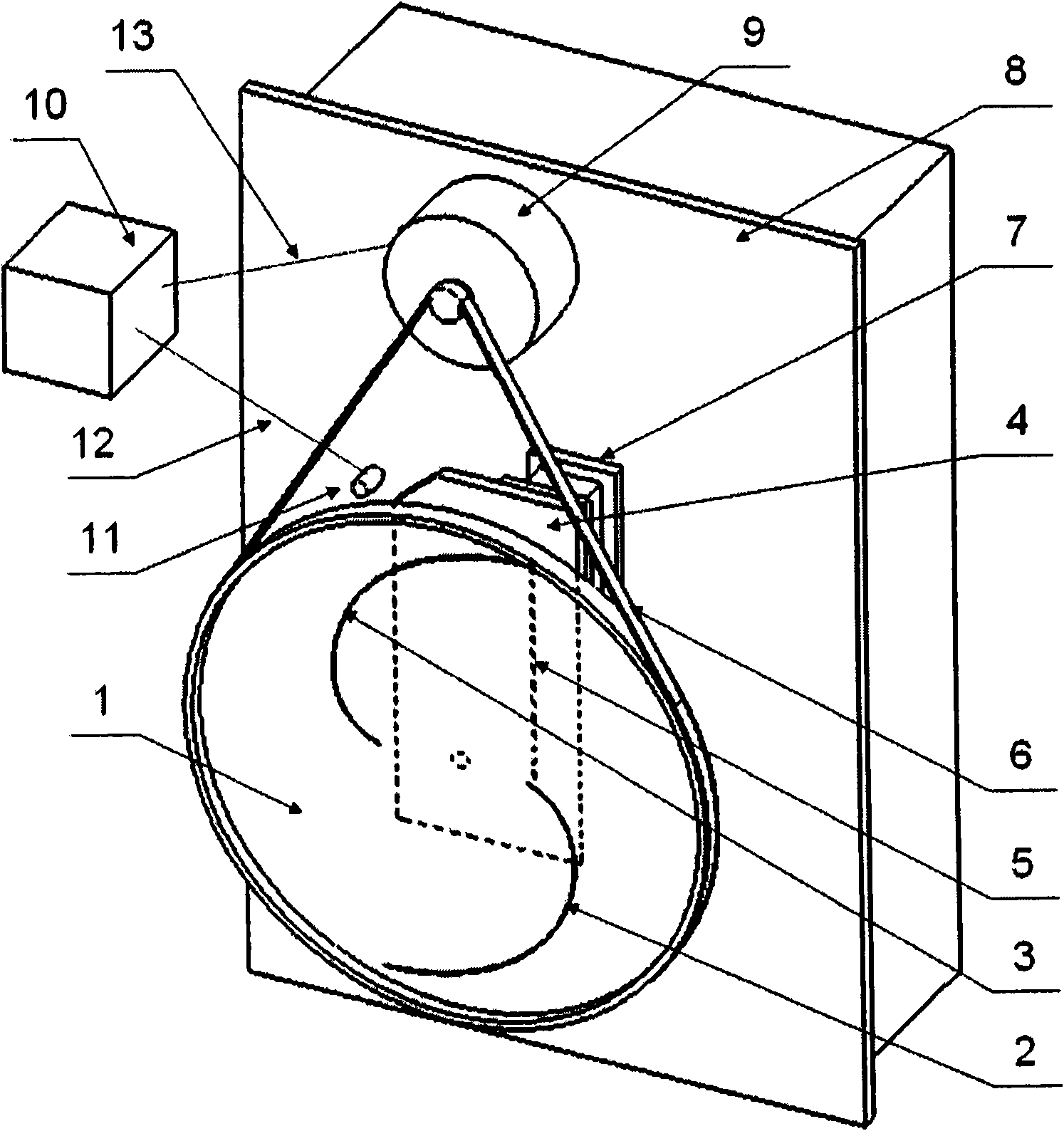
[0013] see figure 1 , the backscattered beam scanning device according to the present invention mainly includes a radiation-shielding rotating plate 1 and a fixed shielding plate 4 respectively arranged in front of the radiation generating device 8 , wherein the fixed shielding plate 4 is closer to the radiation generating device 8 . The radiation-shielding rotating plate 1 is provided with multiple (two in the figure) eccentrically rotating isokinetic slits 2 and 3 . A longitudinal slit 5 is arranged on the fixed shielding plate 4 .

[0014] When the radiation-shielding rotating plate 1 rotates relative to the fixed shielding plate 4 during scanning, the eccentric rotation isokinetic slits 2, 3 on the radiation-shielding rotating plate 1 and the longitudinal slit 5 on the fixed shielding plate 4 jointly form a X-ray collimation hole. As shown in the figure, the positions of the X-ray collimating holes are also different when the radiation-shielding rotating plate 1 rotates ...


PUM


Abstract

The invention discloses a method and a device for ray bundle scanning for back scattering imaging. The scanning device comprises a fixed shield plate and a rotary shield plate which are positioned atthe front of a ray source respectively, wherein the fixed shield plate is fixed relative to the ray source, and the rotary shield plate can be rotated relative to the fixed shield plate; the fixed shield plate and the rotary shield plate are provided with a ray passing region respectively; in the process of rotary scanning of the rotary shield plate, the ray passing region of the fixed shield plate and the ray passing region of the rotary shield plate are continuously crossed to form a scanning collimating hole; the scanning collimating hole is always kept in a preset shape relative to the raysource so that the section shape of the ray bundle passing through the scanning collimating hole is kept unchangeable. The scanning device can complete ideal ray bundle scanning, can implement the uniform scanning for target objects, and can conveniently realize the uniform sampling for the target objects, so longitudinal compressive deformation cannot be generated in obtained back scattering images.

Description

technical field [0001] The invention relates to a ray beam scanning method and device, in particular to an object non-destructive detection method in the application field of nuclear technology. Background technique [0002] In non-destructive testing applications, there are ray transmission imaging and ray backscatter imaging. Backscatter imaging is to scan the object with a ray beam, and the detector receives the scattering signal at the same time, and the scattering image can be obtained by corresponding the scanning position and the scattering signal point during data processing. In the existing flying-spot scanning mechanism, the multi-collimation hole rotating surface of the rotating shield overlaps with the ray scanning sector. If the ray scans longitudinally, the ray scans at a non-uniform speed on the vertical plane object, and the scanning line accelerates at the beginning and end of the scan, which will further expand the scanning spot longitudinally on the basis...

Claims


Application Information

Patent Timeline
Patent Type & Authority Applications(China)
IPC IPC(8): G01N23/04G21K1/02G01B15/00
Inventor 林东沈宗俊刘以农李元景
Owner NUCTECH CO LTD
Why Eureka
Try Eureka