Noise suppressing device, mobile phone and noise suppressing method

A technology of noise suppression and suppression unit, applied in the direction of telephone communication, telephone structure, electrical components, etc., can solve the problems of unstable, uncomfortable sound, and the operation of noise suppression processing is not stable enough, and achieve the effect of preventing the decline of sound quality

Inactive Publication Date: 2010-03-03
FUJITSU LTD
View PDF2 Cites 103 Cited by
  • Summary
  • Abstract
  • Description
  • Claims
  • Application Information

AI Technical Summary

Problems solved by technology

Therefore, the operation of the noise suppression processing is not stable enough
In particular, when the usage mode is switched during the use

Method used


Image

  • Noise suppressing device, mobile phone and noise suppressing method
  • Noise suppressing device, mobile phone and noise suppressing method
  • Noise suppressing device, mobile phone and noise suppressing method

Examples


Embodiment 1

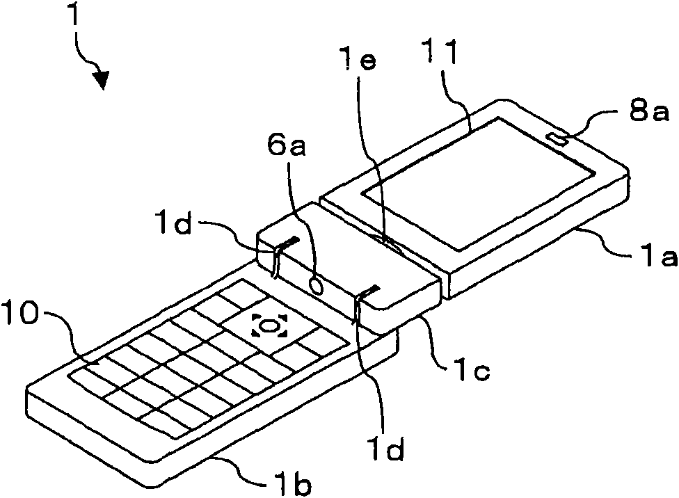
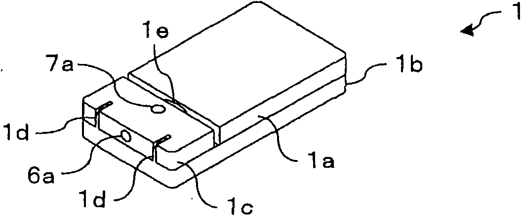
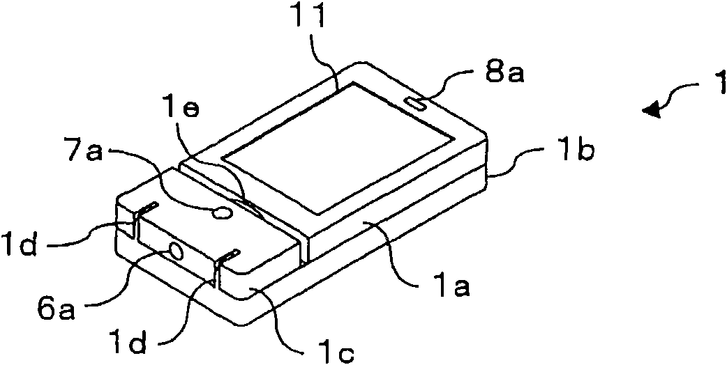
[0048] A mobile phone according to Embodiment 1 will be described below. Figure 1A , Figure 1B and Figure 1C is a schematic diagram describing an example of the configuration of a mobile phone according to Embodiment 1. The mobile phone 1 according to Embodiment 1 is a flip-type mobile phone. Figure 1A An external perspective view of an uncovered mobile phone 1 is depicted, Figure 1B depicts an external perspective view of the mobile phone 1 with the cover closed so that the display unit 11 faces inwardly, and Figure 1C An external perspective view of the mobile phone 1 is depicted with the cover closed so that the display unit 11 faces outward.

[0049] A mobile phone 1 according to Embodiment 1 includes a first housing 1a including a display unit 11, a second housing 1b including an operation unit 10, and a third housing 1c connecting the housings 1a and 1b. The housings 1b and 1c are connected by a hinge portion 1d, and the housings 1a and 1c are connected by a p...

Embodiment 2

[0112] A mobile phone according to Embodiment 2 will be described below. Since the mobile phone according to Embodiment 2 can be realized by a configuration similar to that of the mobile phone 1 according to Embodiment 1, similar configurations are denoted by similar reference numerals, and descriptions of the similar configurations are omitted.

[0113] The mobile phone 1 according to Embodiment 1 has a configuration in which microphone array processing is performed in any of the normal mode and the viewing mode. In contrast, the mobile phone according to Embodiment 2 is configured to perform microphone array processing in the normal mode, and to perform noise suppression processing based on the sound signal received by one microphone 6a in the viewing mode.

[0114] Figure 10 is a functional block diagram describing the functional configuration of the mobile phone 1 according to Embodiment 2. In the mobile phone 1 according to Embodiment 2, the calculating unit 2 has the ...

Embodiment 3

[0125] A mobile phone according to Embodiment 3 will be described below. Since the mobile phone according to Embodiment 3 can be realized by a configuration similar to that of the mobile phone 1 according to Embodiment 1, similar configurations are denoted by similar reference numerals, and descriptions of the similar configurations are omitted.

[0126] The mobile phone 1 according to Embodiment 1 has the following configuration: controls such as image 3 Selection of switches 22 and 23 is shown to operate the first microphone array processing unit 26 in the normal mode of use and the second microphone array processing unit 27 in the viewing mode of use. Different from the above, the mobile phone according to Embodiment 3 has a configuration in which both the first microphone array processing unit 26 and the second microphone array processing unit 27 operate regardless of the usage mode of the mobile phone 1 (i.e., normal mode and viewing method).

[0127] Figure 11 is a ...


PUM


Abstract

A noise suppressing device receives sound signals through a plurality of sound-receiving units and suppresses noise components included in the input sound signals. The noise suppressing device includes a detecting unit which detects a usage pattern of the noise suppressing device from a plurality of usage patterns in which positional relationships of the plurality of sound-receiving units and/or positional relationships between the plurality of sound-receiving units and a target sound source are different from each other, a converting unit which converts using environment information used in anoise suppressing process to each of the sound signals inputted by the plurality of sound-receiving units into using environment information in accordance with a usage pattern detected by the detecting unit and a suppressing unit which performs the noise suppressing process using the using environment information converted by the converting unit to the sound signals.

Description

technical field [0001] The present application relates to a noise suppression device that suppresses a noise component contained in a sound signal obtained by receiving sound, a mobile phone including the noise suppression device, a noise suppression method, and a recording medium. Background technique [0002] There has been developed a microphone array device that includes a plurality of sound receiving units (such as condenser microphones) that convert received sound into sound signals to output the sound signals, and based on the sound output from the sound receiving units, sound signals to perform various sound processing operations. The microphone array device may be configured to perform a delay-add process that synchronously adds sound signals output from the sound receiving unit to make the target sound more prominent with respect to noise (improve the SNR (Signal-to-Noise Ratio) )). The microphone array device can also be configured to suppress noise through sync...

Claims


Application Information

Patent Timeline
IPC IPC(8): G10L21/02H04R3/00H04M1/02G10L21/0208G10L21/0264H04M1/00H04M1/725
CPCG10L21/0208G10L2021/02165G10L2021/02166
Inventor 早川昭二松尾直司片山浩
Owner FUJITSU LTD
Why Eureka
Try Eureka