A sensorized bearing unit

A technology of bearings and sensing devices, applied in the direction of bearing components, bearings of rotating motion, bearings, etc., can solve problems such as no size

Inactive Publication Date: 2010-03-17
AB SKF
View PDF3 Cites 17 Cited by
  • Summary
  • Abstract
  • Description
  • Claims
  • Application Information

AI Technical Summary

Problems solved by technology

However, the electrical connections protrude laterally from the bearing unit, causing size issues in applications where little space is available

Method used


Image

  • A sensorized bearing unit
  • A sensorized bearing unit
  • A sensorized bearing unit

Examples


Embodiment Construction

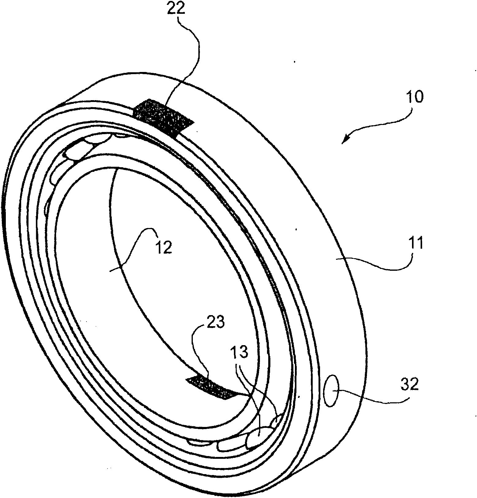
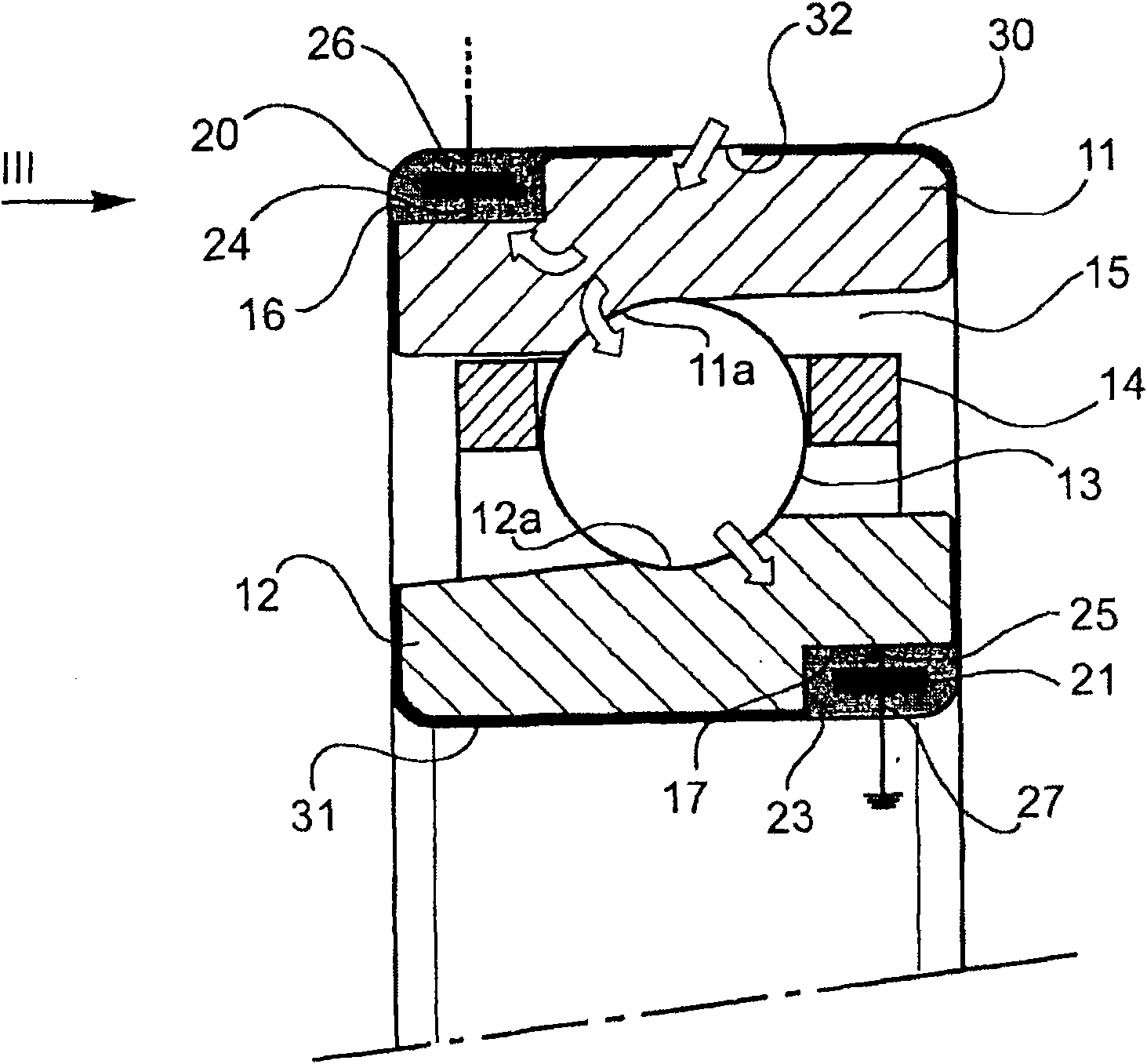
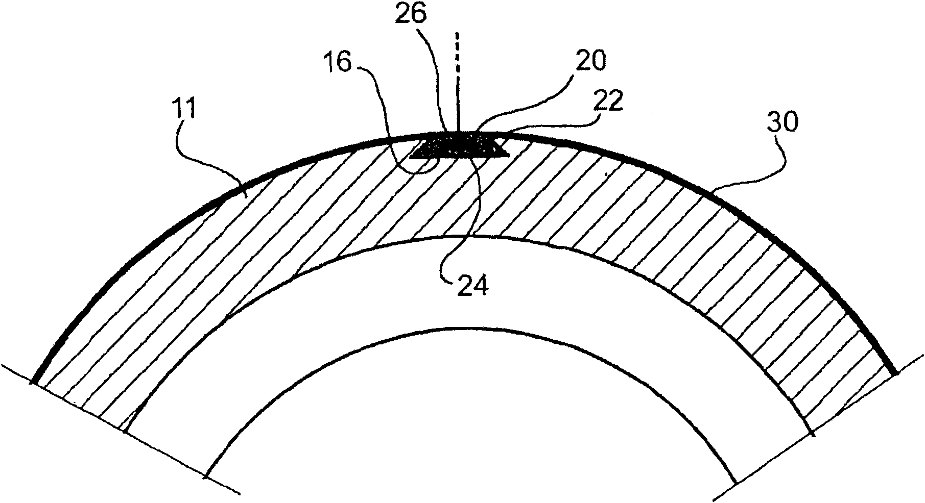
[0011] First refer to figure 1 and 2 , indicated by 10 as a whole is a bearing, which has a fixed outer race 11 and a rotating inner race 12, which respectively form a set of raceways 11a, 12a for two-way rolling elements. In this example, the rolling elements These are balls 13 arranged between the races 11 , 12 and spaced at equal intervals in the circumferential direction by spacer rings 14 . In order to maintain the grease that normally fills the annular gap 15 between the races 11 and 12, sealing means (not shown) may be mounted at both sides of the bearing. The bearing unit shown in the drawings is a so-called first generation type angular contact bearing unit with axially non-approximate races without radial flanges. However, mention of this possible field of application should in no way be construed as limiting the scope of this patent. The invention can also be applied, for example, to flanged bearings.

[0012] The bearing unit 10 is equipped with one or more sen...


PUM


Abstract

In a bearing unit (10), at least one sensor device (20, 21) is locked in a recess (16, 17) formed in a superficial zone of one of the races (11, 12). The stationary race (11) is partially covered withan electrically insulating material (30). An uncovered surface zone (32) is provided for electrically connecting the stationary race (11) to an electrical supply source located outside the bearing unit.

Description

technical field [0001] The invention relates to a sensor-equipped bearing unit of the type indicated in the preamble of claim 1 . Background technique [0002] It is known that some bearing units are equipped with sensors, such as rotation sensors, load sensors, temperature sensors, etc., in order to detect several important physical parameters when monitoring the operation of the bearing. Typically, these sensors are mounted at one side of the bearing unit and require electrical connectors to power the sensors and transmit data detected by the sensors to remote instrumentation. In some cases, the sensor is arranged in one of the seals that laterally close the annular gap between the bearing races. However, the electrical connections protrude laterally from the bearing unit, causing size problems in applications where little space is available. See, for example, EP 0464403A1 and EP 0498298A1. [0003] US 6948856B2 discloses bearing units in which sensors are located in gr...

Claims


Application Information

Patent Timeline
Patent Type & Authority Applications(China)
IPC IPC(8): G01P3/44
CPCG01L5/0009F16C19/163F16C19/52F16C33/586F16C2202/30G01P3/443F16C19/00F16C33/76G01P3/44
Inventor 戴维·乔达纳
Owner AB SKF
Why Eureka
Try Eureka