Device, method, and control program for refractive surgery

A technology for refractive surgery and control procedures, applied in the field of devices for refractive surgery, which can solve problems such as the root cause of errors

Active Publication Date: 2010-03-24
ALCON INC
View PDF2 Cites 11 Cited by
  • Summary
  • Abstract
  • Description
  • Claims
  • Application Information

AI Technical Summary

Problems solved by technology

[0014] If, in the prior art, the center of the pupil was used as the center of ablation during refractive surgery, one would have a cascade of systemic sources of error

Method used


Image

  • Device, method, and control program for refractive surgery
  • Device, method, and control program for refractive surgery

Examples


Embodiment Construction

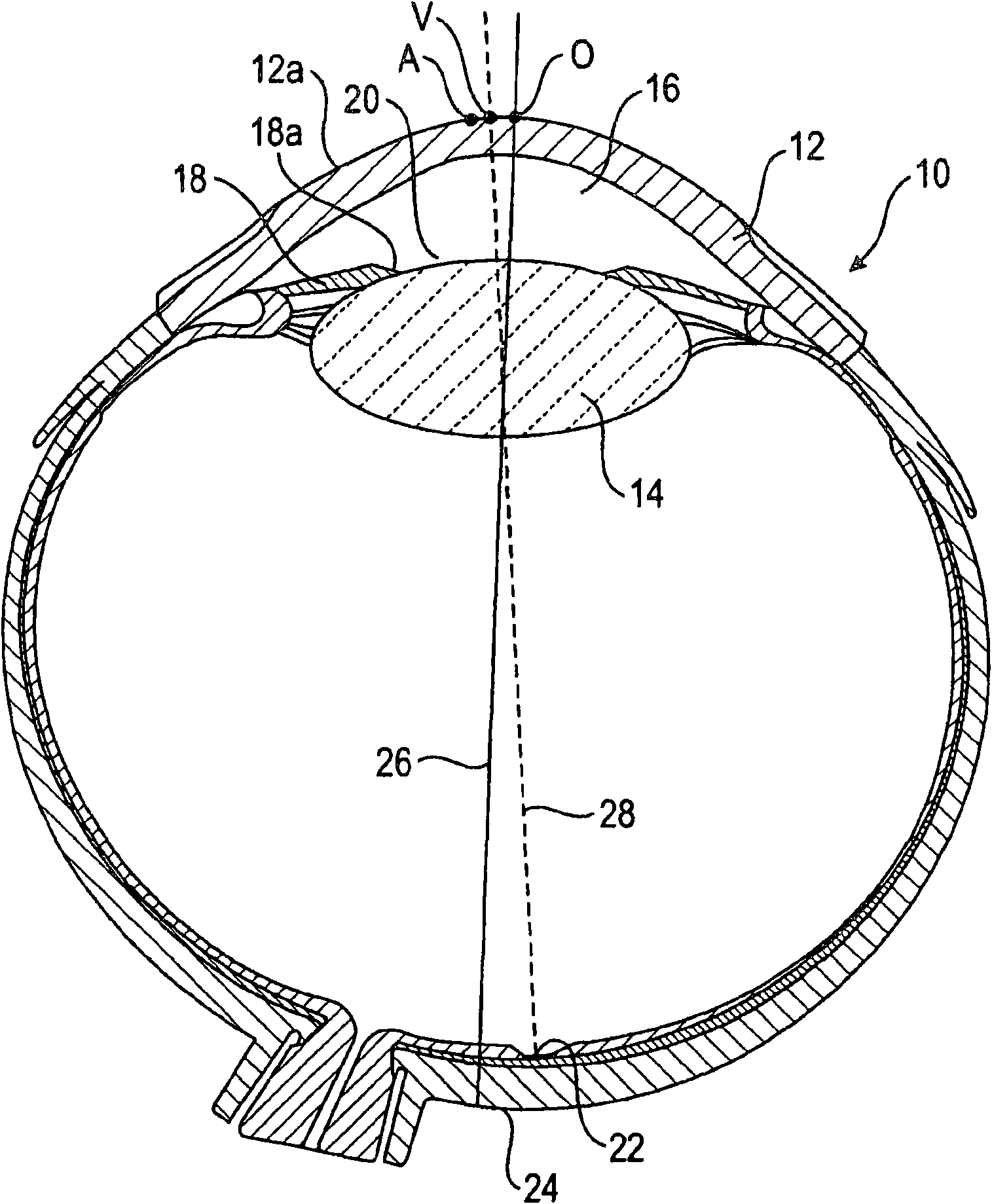
[0048] according to figure 1 A horizontal cross-sectional view of eye 10 schematically shows cornea 12, lens 14, anterior chamber 16, iris 18, its edge 18a delimiting pupil 20, fovea 22, macula 24, optical axis 26, and visual axis 28.

[0049] Optical axis 26 intersects front face 12a of cornea 12 at position O. The visual axis 28 intersects the front face 12a of the cornea at a position V.

[0050] The apex A of the cornea 12 is generally neither at position O nor at position V, but as in figure 1 Schematically shown in , the intersection V of the visual axis (axis of vision) is located between the vertex A and the intersection O of the optical axis and the corneal surface. At the same time, V is generally closer to A than to O. The present invention takes advantage of this anatomical generality.

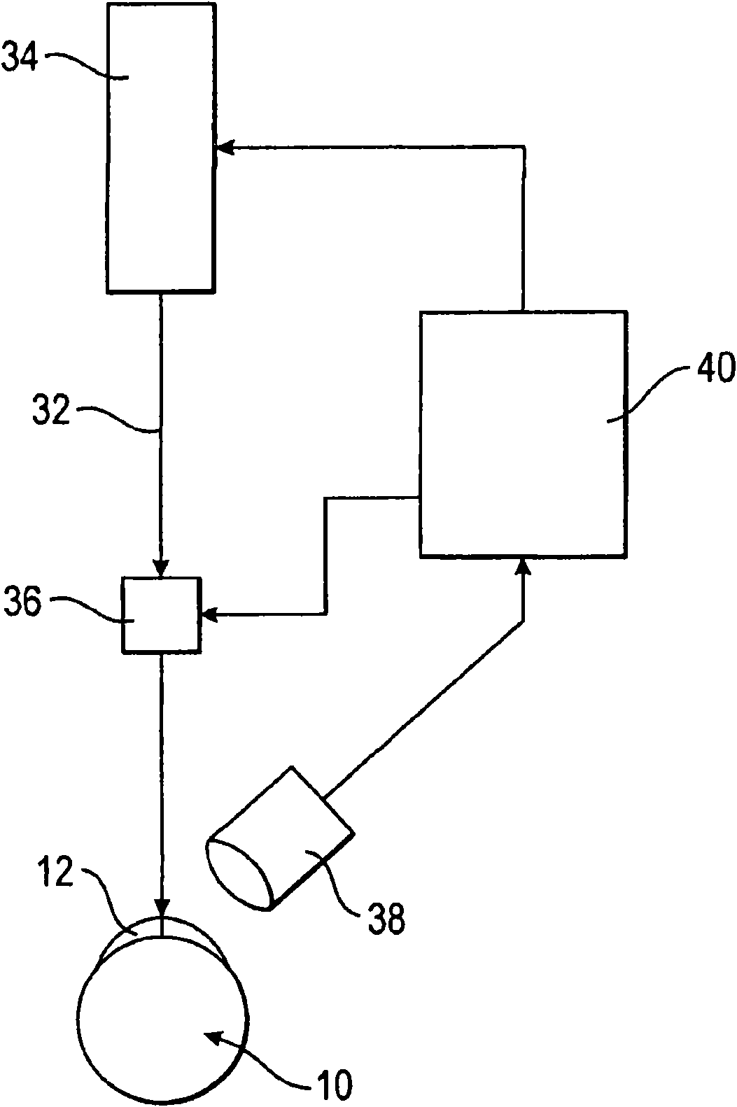
[0051] figure 2 A device for refractive surgery is schematically shown with a laser beam source 34 which emits laser beam 32 which is aimed at the eye 10 to be treated by mea...


PUM


Abstract

The invention relates to a device and a method for refractive surgery, particularly LASIK, provide that the apex of the cornea is the basis for the ablation center for the refractive procedure. To this end, the dependency of the position of the apex on properties of the pupil is determined in the eye to be treated, and the position of the ablation center for the refractive surgery is computed fromthis dependency by means of the properties of the pupil measured.

Description

technical field [0001] The invention relates to a device for refractive surgery, a control program for such a device and a method for generating such a control program. Background technique [0002] In the professional world, "refractive surgery" is understood as changing the imaging properties of the optical system "eye" by means of laser beams. Laser rays change the refractive properties of one or more components of the eye. Since the cornea is primarily decisive for the imaging properties of the eye, refractive surgery is used, in particular, to perform orthokeratology. [0003] A well-known example of such corneal reshaping for changing the refractive properties of the cornea is LASIK (Laser In Situ Keratomileusis). The invention relates in particular to the LASIK technique. Furthermore, the present invention can also be commonly used in PRK (refractive keratectomy) and EPI-LASIK (laser in situ keratomileusis with microknife). The invention can also be used when usin...

Claims


Application Information

Patent Timeline
Patent Type & Authority Applications(China)
IPC IPC(8): A61F9/01
CPCA61B3/112A61F9/00804A61F9/00827A61F2009/00844A61F2009/00846A61B3/113A61F2009/00872A61F9/008A61B18/20
Inventor 西西莫斯·莱莫尼斯
Owner ALCON INC
Why Eureka
Try Eureka