Rotor mounting device and rotor mounting method

A technology for installing devices and rotors, which is applied to electromechanical devices, manufacturing stator/rotor bodies, and controlling mechanical energy. Simple, avoid the effect of complex construction

Inactive Publication Date: 2010-03-31
HONDA MOTOR CO LTD
View PDF3 Cites 6 Cited by
  • Summary
  • Abstract
  • Description
  • Claims
  • Application Information

AI Technical Summary

Problems solved by technology

Therefore, there is a problem that the structure of the installation device is complicated and the installation work process becomes complicated.

Method used


Image

  • Rotor mounting device and rotor mounting method
  • Rotor mounting device and rotor mounting method
  • Rotor mounting device and rotor mounting method

Examples


Embodiment Construction

[0030] Next, an embodiment of the present invention will be described with reference to the drawings.

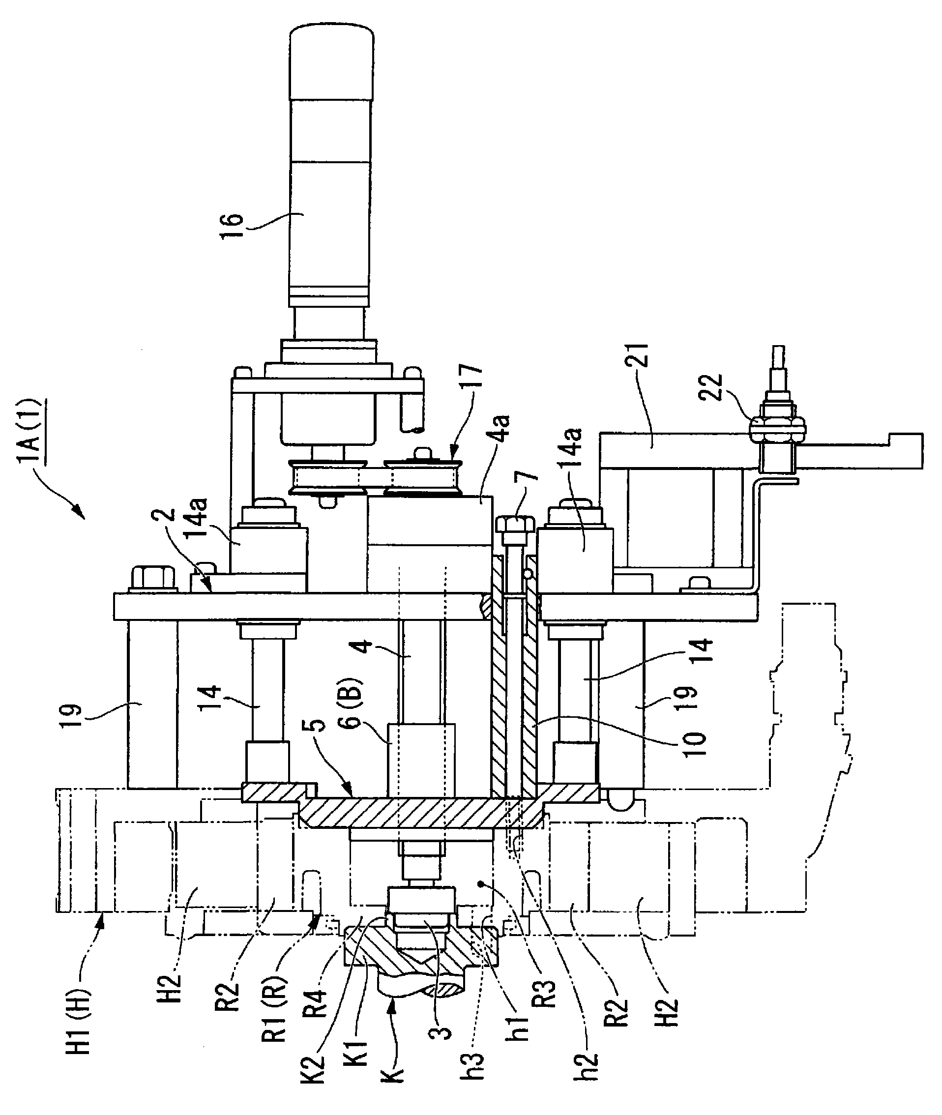
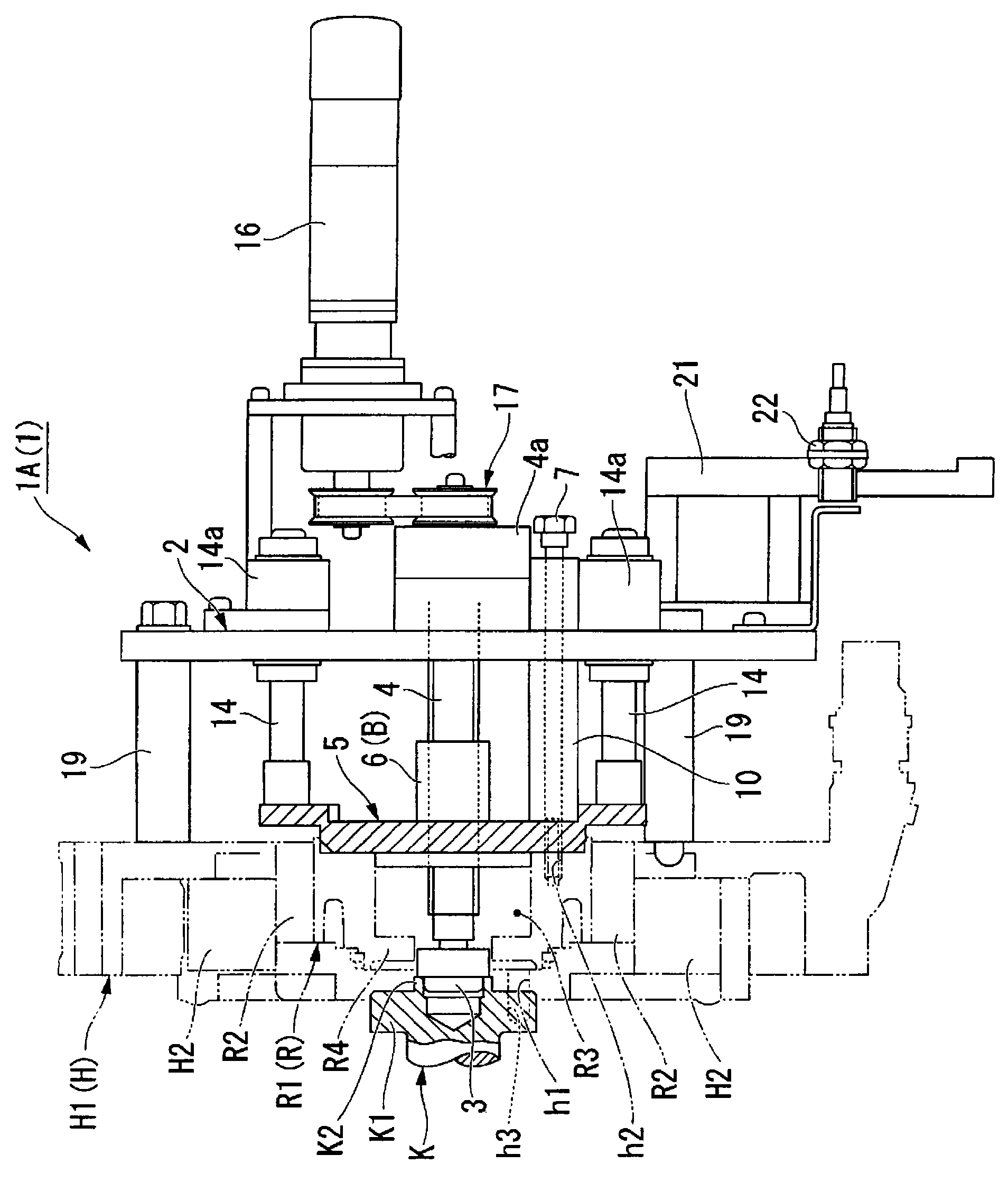
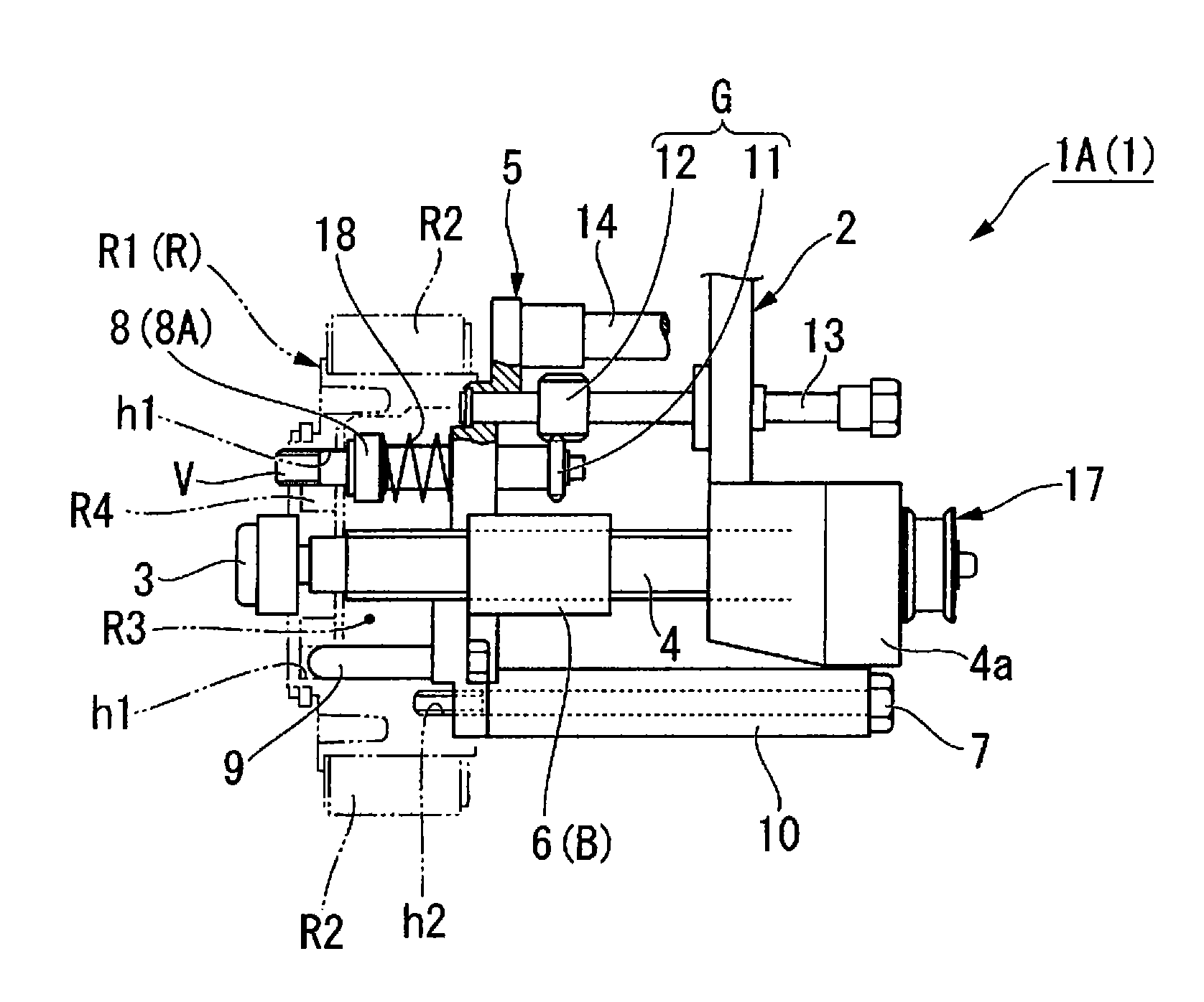
[0031] Figure 7 Indicates a rotor mounting device 1 for inserting the rotor R of the motor M into the engine (internal combustion engine) E and pre-installed in the assembly process of a power unit for a hybrid vehicle in which the electric motor M and the crankshaft K of the engine (internal combustion engine) E are coaxially arranged. In the rotor casing H of the motor M on E, and connect the rotor R with the crankshaft K of the engine E.

[0032] The engine assembly 15 is composed of an engine E and a rotor case H mounted on the engine E in advance, and is conveyed by a conveyor C. As shown in FIG. When the engine assembly 15 is transported to a predetermined rotor mounting position P1 , the rotor R is mounted by the rotor mounting device 1 . The rotor mounting device 1 includes a manipulator 20 and a device main body 1A integrally provided with the top end of the mani...


PUM


Abstract

A rotor mounting device for inserting the rotor of a motor into a rotor housing which is mounted to an engine and coaxially mounting the rotor to a crankshaft. The rotor mounting device is provided with a rotor supporting member, a rotor positioning member engaging with some of the bolt insertion holes formed in the rotor to position the rotor, a temporarily fixing bolt for temporarily fixing therotor to the rotor supporting member, a driving shaft having a front end engaged with an end of the crankshaft and axially movably supporting the rotor supporting member through a screw mechanism, a base member for rotatably supporting the base end side of the driving shaft and allowing the rotor supporting member to approach and separate from the base member, a base positioning member engaging with the rotor housing, and a fastening mechanism engaging with the head of a connecting bolt inserted through at least one of the bolt insertion holes and supported by the rotor supporting member so asto urge the connecting bolt to the rotor side.

Description

technical field [0001] The invention relates to a rotor installation device and a rotor installation method. [0002] This application claims the priority of Japanese Patent Application No. 2008-129696 with a filing date of May 16, 2008, the content of which is incorporated herein. Background technique [0003] In the prior art, when the rotor with magnets is installed (inserted) into the rotor housing with stator coils, in order to prevent the outer circumference of the rotor (magnets) from contacting the inner circumference of the rotor housing (stator coils) due to magnetic attraction, a fixed Type or movable mounting device, so that the rotor can only move in the axial direction relative to the rotor housing (for example, refer to patent documents 1 and 2). [0004] Patent Document 1: Japanese Invention Patent Laid-Open Publication No. Hei 7-67299 [0005] Patent Document 2: Japanese Invention Patent Laid-Open Publication No. 2002-210619 [0006] The prior art describ...

Claims


Application Information

Patent Timeline
IPC IPC(8): H02K15/02
CPCH02K15/02Y10T29/49009Y10T29/49011Y10T29/49012Y10T29/53143Y10T29/53161H02K7/14H02K7/1815H02K15/03
Inventor 竹原义昭井口清史
Owner HONDA MOTOR CO LTD
Why Eureka
Try Eureka