Method for determining combined insulation thermal resistance of cable and method for calculating current-carrying capacity of cable

A technology of combining insulation and determining methods, applied in the direction of measuring resistance/reactance/impedance, measuring electrical variables, measuring electricity, etc., can solve the problems of inaccurate current carrying capacity of cables, inaccurate calculation of insulation thermal resistance, etc.

Active Publication Date: 2010-04-07
GUANGZHOU POWER SUPPLY BUREAU GUANGDONG POWER GRID CO LTD +1
View PDF0 Cites 23 Cited by
  • Summary
  • Abstract
  • Description
  • Claims
  • Application Information

AI Technical Summary

Problems solved by technology

In fact, generally high-voltage cables use corrugated metal sheaths, and this part is not a concentric cylinder structure. In addition, the thermal resistance coefficient of XLPE has a great relationship with its operating temperature, especially in the range of operating temperatures between 80 ° C and 120 ° C. XLPE The thermal resistance coefficient is not constant at 3.5K m / W. In addition, the part between the conductor and the metal sheath is not only XLPE insulation, but also includes a buffer zone, a water blocking zone, an air gap, etc., and its thermal resistance coefficient Generally much greater than 3.5K m / W, so the calculation of thermal insulation resistance is inaccurate, and the ampacity of the cable obtained according to thermal insulation resistance is also inaccurate

Method used


Image

  • Method for determining combined insulation thermal resistance of cable and method for calculating current-carrying capacity of cable
  • Method for determining combined insulation thermal resistance of cable and method for calculating current-carrying capacity of cable
  • Method for determining combined insulation thermal resistance of cable and method for calculating current-carrying capacity of cable

Examples


Embodiment Construction

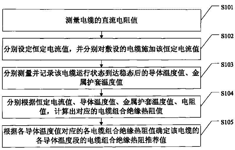
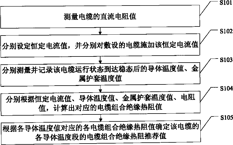
[0021] Considering the strong correlation between cross-linked polyethylene insulation material and temperature, the irregular structure of corrugated sheathed cables, the existence of air gaps in the metal sheath, and the comparison between the thermal resistivity of materials such as buffer layer water-blocking tape and the main insulation The present invention proposes the concept of combined insulation, that is, each layer between the conductor and the metal sheath is regarded as a whole, and the thermal resistance of the whole is used to express its role in cable heat dissipation, in order to achieve accurate cable ampacity calculate.

[0022] In order to obtain the combined insulation thermal resistance value of the cable, the present invention suggests that when the cable leaves the factory, a section of the cable should be intercepted to carry out the temperature rise test of a single cable for air laying and direct buried laying, and the recommended value of the combin...


PUM


Abstract

The invention discloses a concept of combined insulation of a cable, and provides a method for determining the combined insulation thermal resistance of the cable. The combined insulation of the cable comprises every layer between a conductor and a metallic sheath, namely the layers between the conductor and the metallic sheath are regarded as a whole body, different constant current values are applied to the cable in a laying test, and a recommended value for the combined insulation thermal resistance of the cable is determined by combining a constant current value, a resistance value of the conductor and the like according to a conductor temperature value and a metallic sheath temperature value measured under a condition with different constant current values, wherein the recommended value for the combined insulation thermal resistance of the cable is a parameter value obtained by comprehensively considering materials of each layer between the conductor and the metallic sheath, so the recommended value is closer to the actual condition of the insulation thermal resistance of the cable, and the obtained current-carrying capacity of the cable is more accurate when the current-carrying capacity of the cable is deduced and calculated according to the recommended value for the combined insulation thermal resistance of the cable.

Description

technical field [0001] The invention relates to the technical field of power cables, in particular to a method for determining the combined insulation thermal resistance of cables and a method for calculating the ampacity of cables. Background technique [0002] In the field of power cable technology, considering the importance of the cable ampacity, the specific performance is that the power design department selects the cable and designs the cable line according to the cable ampacity, and the operation part controls the load of the cable line according to the cable ampacity. Therefore, the accurate calculation and determination of the cable ampacity is particularly important. In the way of calculating the ampacity of cables in the prior art, one of the parameters that needs to be applied is insulation thermal resistance. According to the method given in the IEC60287 standard, the part between the conductor and the metal sheath, including the conductor shield , cross-linke...

Claims


Application Information

Patent Timeline
Patent Type & Authority Applications(China)
IPC IPC(8): G01R27/02G01R31/00
Inventor 王晓兵牛海清汤毅张尧罗真海张泽华
Owner GUANGZHOU POWER SUPPLY BUREAU GUANGDONG POWER GRID CO LTD
Why Eureka
Try Eureka