
Method for simulating load test with transformer substation bus differential protection current

A busbar differential protection and test method technology, applied in the direction of measuring electricity, measuring electrical variables, instruments, etc., can solve problems such as inability to judge the correctness, small current in the secondary circuit of the busbar difference, inconsistent completion time of substation and line installation, etc.

Active Publication Date: 2010-04-14
STATE GRID CORP OF CHINA +1
View PDF0 Cites 25 Cited by
  • Summary
  • Abstract
  • Description
  • Claims
  • Application Information

AI Technical Summary

Problems solved by technology

The on-load test must be done before the bus differential protection is put into operation to ensure the correctness of the bus differential protection current circuit. Because the load near the newly built substation is not large or the installation completion time of the substation and the line is not consistent, the busbar during the load test of the substation will occur. The current of the secondary circuit is small, and the correctness cannot be judged, or the situation where the line is not connected and can only be done after the line is formed

Method used


Image

  • Method for simulating load test with transformer substation bus differential protection current
  • Method for simulating load test with transformer substation bus differential protection current
  • Method for simulating load test with transformer substation bus differential protection current

Examples


Embodiment Construction

[0015] 1. Transformation ratio test of bus differential with load circuit ( figure 2 shown)

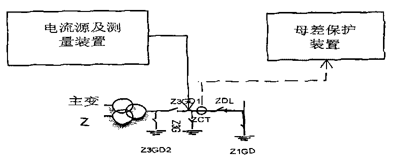
[0016] For the transformation ratio test of the bus differential with load circuit (take the main transformer CT as an example), the outlet pressure plate of the protection device is withdrawn, the main transformer isolating switch Z3G is disconnected, the large current test device is connected between the grounding isolating switch 3GD1 and ZCT, and the main transformer circuit breaker ZDL and the main transformer I female grounding isolating switch Z1GD are closed (check the control circuit of the circuit during the operation process, and the auxiliary contacts related to protection can be found to be open circuit or poor contact of the circuit and the correctness of the wiring), and the current of each phase can be passed in respectively. Check the correctness of phases A, B, and C (neutral wire grounding).

[0017] The current displayed in the high-current test device is compare...


PUM


Abstract

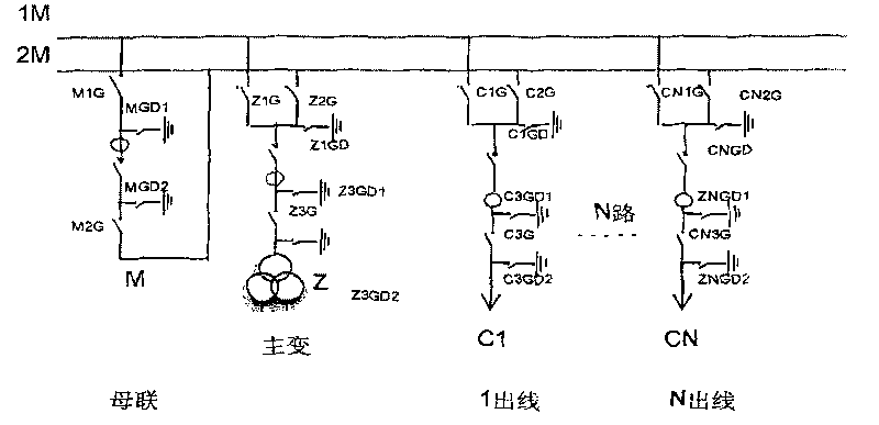
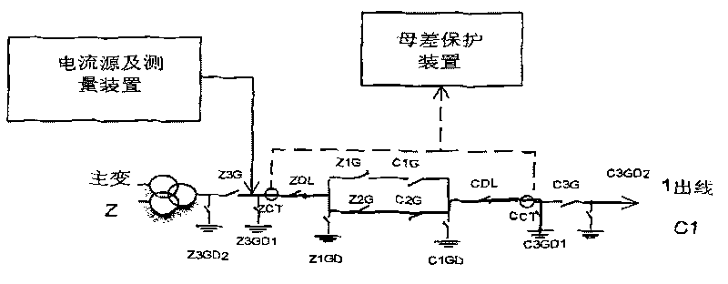
The invention discloses a method for simulating a load test with transformer substation bus differential protection current. A heavy-current device is utilized to replace a power transmission power supply to be accessed between a main transformer earthing isolating switch and a main transformer current mutual inductor; an outgoing earthing isolating switch is utilized to simulate load; a heavy-current device three-phase wiring zero line is grounded to simulate different faults of one phase and faults between phases. The invention can replace a load test of a bus differential current loop and can simulate fault states and change the traditional transformer substation bus differential protection current loop indirect test methods. The transformer substation double-bus differential protection current loop, a relative breaker, the isolating switch and a current mutual inductor control operation loop are precisely simulated before power is transmitted, and a bus differential protection normal running state and fault state are simulated well so as to ensure that the protection current loop is in a correct state before the power is transmitted. Defects which can be possibly found in transformer substation load test are eliminated. The invention is more accurate, safer and more reliable.

Description

Technical field: [0001] The invention relates to a load test method for a substation bus differential protection current loop simulation with load in a power system. Background technique: [0002] With the development of the national economy, substations have sprung up like mushrooms after rain. Now the busbars with voltage levels above 110kV ~ 220kV generally use busbar protection, and busbars are important equipment in substations. The correctness of its action is related to the circuit breaker of the primary equipment, the disconnector, the current transformer, the test of the protection device, the secondary wiring, and the DC control circuit. The traditional current circuit test adopts separate and segmented test methods, such as the transformation ratio, polarity, protection test and secondary circuit test of the current transformer. Therefore, the regulations stipulate. The on-load test must be done before the bus differential protection is put into operation to en...

Claims


Application Information

Patent Timeline
Patent Type & Authority Applications(China)
IPC IPC(8): G01R31/00G01R31/02
Inventor 金志荣张海帆顾建军季建张新民缪晓卫
Owner STATE GRID CORP OF CHINA
Learn More