A standard device of a cable fault flash tester

A technology for cable faults and standard devices, which is applied to measurement devices, fault locations, and fault detection by pulse reflection method. Problems, stable and reliable performance, high degree of automation effect

Active Publication Date: 2011-12-14
STATE GRID ELECTRIC POWER RES INST
View PDF0 Cites 2 Cited by
  • Summary
  • Abstract
  • Description
  • Claims
  • Application Information

AI Technical Summary

Problems solved by technology

This traditional calibration method has many deficiencies, mainly because: as a standard instrument, the length of the physical cable will change greatly due to the influence of temperature, and due to its own elasticity and human error, the length calibration work is complicated and accurate At the same time, the physical cables are often made of single or fixed insulating materials, and the types of cables that can be simulated are not rich. If you want to simulate cables with multiple materials, the cost will be greatly increased
[0004] To sum up, the current domestic traditional standard devices and calibration methods are deficient in working principle and traceability, and the accuracy cannot meet the requirements
Considering that the nominal maximum allowable error of a large number of cable fault flash detectors on the market can reach ± ​​(1% reading ± 20 meters), and the above-mentioned traditional method of using physical cables as standard instruments is limited by accuracy and convenience, It is difficult to carry out convenient and efficient calibration work on the cable fault flash detector

Method used


Image

  • A standard device of a cable fault flash tester
  • A standard device of a cable fault flash tester
  • A standard device of a cable fault flash tester

Examples


Embodiment Construction

[0024] The present invention will be further described below in conjunction with the accompanying drawings.

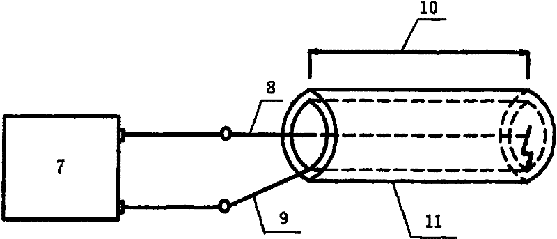
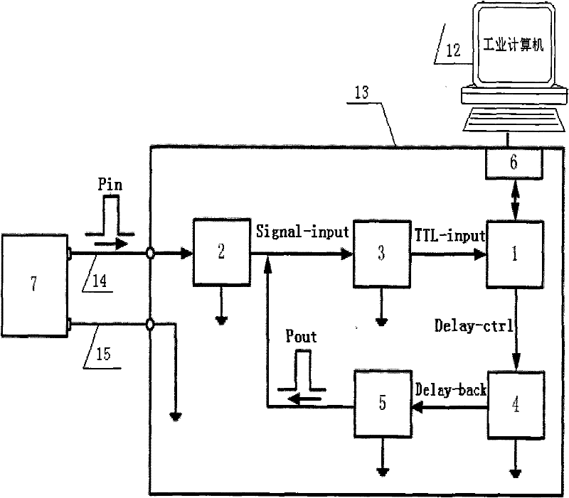
[0025] Marks in the figure: 1-control module, 2-cable core wire multiplexing module, 3-input signal conditioning module, 4-signal delay feedback module, 5-high-speed amplification and drive module, 6-communication interface, 7-by Flash tester for cable fault detection, 8, 14-cable core wire, 9-cable shielding layer, 10-cable fault distance, 11-physical cable, 12-upper computer, 13-lower computer, 15-cable shielding layer, 16- Analog door.

[0026] see figure 1Shown is a schematic diagram of the principle of the calibration method of the traditional cable fault flash detector based on the physical method. In this method, the physical cable 11 is used as a standard instrument, and the length of the physical cable is calibrated with a length measuring instrument in advance. After the calibration, the physical cable is used to calibrate the fault detector of the tested c...


PUM


Abstract

The utility model relates to a standard device of a cable fault flash tester, which belongs to the field of calibration, verification and detection of electric test instruments. Including the upper computer and the lower computer, the core circuit of the lower computer mainly includes: control module, cable core wire multiplexing module, input signal conditioning module, signal delay feedback module, high-speed amplification and drive module, the relationship between each module is: The cable fault flash tester is connected to the cable core wire multiplexing module, the cable core wire multiplexing module, the input signal conditioning module, the control module, the signal delay feedback module, the high-speed amplification and driving module are connected in sequence, and the high-speed amplification and driving module is connected to the input signal conditioning module. Its core design idea is to simulate the time-domain reflection characteristics of physical cables through the "passive feedback loop", and use the invention to perform reasonable and efficient calibration work on the main measurement functions of the cable fault flash detector, namely, the distance measurement function and the speed measurement function.

Description

technical field [0001] The invention relates to a standard device of a cable fault flash tester, which belongs to the field of calibration, verification and detection of electric power testing instruments. Background technique [0002] In order to measure and locate the cable fault distance, many electric power testing instrument manufacturers have developed a cable fault flash tester. The cable fault flash tester is a working measuring instrument, and the essential measurement parameter is the amount of time. In the electric power industry standard "DL / T849.1-2004 General Technical Conditions for Special Test Instruments for Power Equipment Part 1: Cable Fault Flash Tester", it is clearly defined It is required to calibrate and test the ranging and speed measuring functions of the cable fault flash detector. However, similar to many pre-test instruments, due to its strong pertinence and special interface, its measurement characteristics are difficult to trace to the superi...

Claims


Application Information

Patent Timeline
Patent Type & Authority Patents(China)
IPC IPC(8): G01R35/00G01R31/11
Inventor 雷民张军项琼包玉树王斯琪齐聪
Owner STATE GRID ELECTRIC POWER RES INST
Why Eureka
Try Eureka