Multi-line trl calibration method and terminal equipment

A calibration method and technology of calibration parts, which are applied in the direction of instruments, measuring devices, and measuring electrical variables, etc., and can solve the problems of low measurement accuracy of S parameters

Active Publication Date: 2020-03-24
THE 13TH RES INST OF CHINA ELECTRONICS TECH GRP CORP
View PDF9 Cites 0 Cited by
  • Summary
  • Abstract
  • Description
  • Claims
  • Application Information

AI Technical Summary

Problems solved by technology

[0005] In view of this, embodiments of the present invention provide a multi-line TRL calibration method and terminal equipment to solve the problem of low measurement accuracy of S-parameters in multi-line TRL calibration in the prior art

Method used


Image

  • Multi-line trl calibration method and terminal equipment
  • Multi-line trl calibration method and terminal equipment
  • Multi-line trl calibration method and terminal equipment

Examples


Embodiment 1

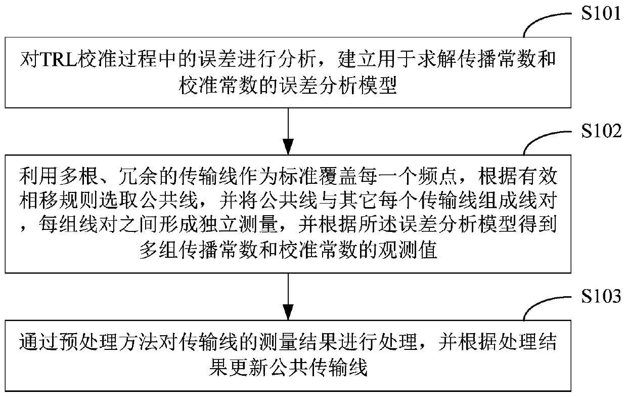
[0172] figure 1 The implementation flow of the multi-line TRL calibration method provided by Embodiment 1 of the present invention is shown, and the details are as follows:

[0173] Step S101 , analyzing the errors in the TRL calibration process, and establishing an error analysis model for solving propagation constants and calibration constants.

[0174] In this step, the error in the TRL calibration process is analyzed, and the process of establishing an error analysis model for solving the propagation constant and the calibration constant is:

[0175] The concatenated transfer matrix M of the i-th calibration piece measured by Yaneti i for

[0176]

[0177] Among them, T i is the actual transmission matrix of the calibration part i, X and Y are the transmission matrix of the error network to be obtained, that is, the calibration constant; Indicates that the direction of signal transmission is opposite to that of Y. For example, if Y represents the transfer matrix...

Embodiment 2

[0270] Corresponding to the multi-line TRL calibration method described in the above embodiment, Figure 7 A schematic diagram of the operating environment of the multi-line TRL calibration program provided by the embodiment of the present invention is shown. For ease of description, only the parts related to this embodiment are shown.

[0271] In this embodiment, the multi-line TRL calibration program 200 is installed and runs in the terminal device 20 . The terminal device 20 may include, but not limited to, a memory 201 and a processor 202 . Figure 7 Only terminal device 20 is shown with components 201-202, but it is to be understood that implementation of all of the illustrated components is not required and that more or fewer components may instead be implemented.

[0272] The storage 201 may be an internal storage unit of the terminal device 20 in some embodiments, for example, a hard disk or a memory of the terminal device 20 . The memory 201 may also be an external...


PUM


Abstract

The invention provides a multiline TRL calibration method and terminal equipment. The method comprises steps: errors in a TRL calibration process are analyzed, and an error analysis model for solvinga propagation constant and a calibration constant is established; multiple redundant transmission lines are used as a standard to cover each frequency point, a public line is selected according to aneffective phase shift rule, the public line and each other transmission line form a line pair, independent measurement is formed in each line pair, and according to the error analysis model, the observation values of multiple groups of propagation constants and calibration constants are obtained; and through a preprocessing method, the measurement results of the transmission lines are processed, and a public transmission line is updated according to the processing result. The above method and the terminal equipment can improve the on-wafer S parameter test accuracy.

Description

technical field [0001] The invention belongs to the technical field of microwave characteristic measurement of crystal original level semiconductor devices, and in particular relates to a multi-line TRL calibration method and terminal equipment. Background technique [0002] A large number of "on-chip S-parameter test systems" equipped in the microelectronics industry need to use on-chip calibration components for vector calibration before use. The types of calibration components include SOLT (Short-Open-Load-Thru), TRL (Thru-Reflect -Line), LRRM (Line-Reflect-Reflect-Match), etc. There are two main reasons that affect the calibration accuracy in Kataya Networks: one is the system error introduced by the system reference impedance, and the other is the repeatability error caused by the contact between the probe and the DUT. [0003] The SOLT calibration reference impedance is the load (Load), and the characteristic impedance of the straight-through line is designed to be eq...

Claims


Application Information

Patent Timeline
Patent Type & Authority Patents(China)
IPC IPC(8): G01R35/00
CPCG01R35/005
Inventor 王一帮栾鹏吴爱华梁法国霍烨
Owner THE 13TH RES INST OF CHINA ELECTRONICS TECH GRP CORP
Why Eureka
Try Eureka