Onsite calibration method for synchro transmitter or analyzer

A technology of synchronous transmission and on-site calibration, applied to instruments, measuring devices, measuring electrical variables, etc., can solve the problems of high calibration environment and standard requirements, inability to achieve calibration requirements, and low calibration accuracy, and achieve stable and reliable calibration process. , easy to implement and wide adaptability

Active Publication Date: 2015-04-29
HARBIN
View PDF4 Cites 0 Cited by
  • Summary
  • Abstract
  • Description
  • Claims
  • Application Information

AI Technical Summary

Problems solved by technology

Although the above method has high calibration accuracy, it has relatively high requirements on the calibration environment and standards. It is generally only suitable for synchronization / analysis equipment with high calibration accuracy in the calibration laboratory environment, and cannot be implemented in the work or experiment site. Calibration needs
At present, the synchronous transmitter / resolver commonly used in experiments / work is generally embedded in large-scale experimental equipment, and its calibration accuracy is not high, and it is difficult to disassemble and send to the calibration laboratory, so the above method cannot be used for calibration

Method used


Image

  • Onsite calibration method for synchro transmitter or analyzer
  • Onsite calibration method for synchro transmitter or analyzer
  • Onsite calibration method for synchro transmitter or analyzer

Examples


Embodiment 1

[0030] The steps of the calibration method involved in the present invention are:

[0031] Step 1: Selection of Calibration Equipment

[0032] Step 1.1: Select the master standard for calibration

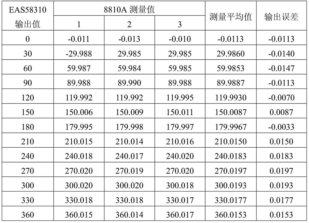
[0033] The model of the angular position indicator is 8810A: the technical parameters are: angle measurement range: 0~360°; resolution: 0.0001°; measurement allowable error: ±0.004°.

[0034] Step 1.2: Supporting Equipment

[0035] The parameters for selecting the onboard power supply are power supply frequency: 400Hz, power supply voltage: 115V or 26V variable.

[0036] Step 2: Calibration Preparation

[0037] Step 2.1: Power on and warm up

[0038] As the standard angular position indicator and the large equipment where the calibrated synchronous transmitter / resolver is located, it is normally connected to 220V, 50Hz mains power. Warm up for 15 minutes after starting up.

[0039] Step 2.2: Reference Signal Input

[0040] After power on, according to the use requirements of ...

Embodiment 2

[0052] Step 1: Selection of Calibration Equipment

[0053] Step 1.1: Select the master standard for calibration

[0054]The model of the angular position indicator is 8810A: the technical parameters are: angle measurement range: 0~360°; resolution: 0.0001°; measurement allowable error: ±0.004°.

[0055] Step 1.2: Supporting Equipment

[0056] The parameters for selecting the onboard power supply are power supply frequency: 400Hz, power supply voltage: 115V or 26V variable.

[0057] Step 2: Calibration Preparation

[0058] Step 2.1: Power on and warm up

[0059] As the standard angular position indicator and the large equipment where the calibrated synchronous transmitter / resolver is located, it is normally connected to 220V, 50Hz mains power. Warm up for 15 minutes after starting up.

[0060] Step 2.2: Reference Signal Input

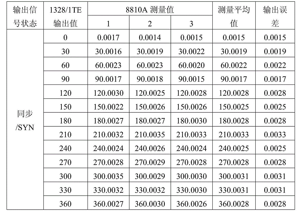
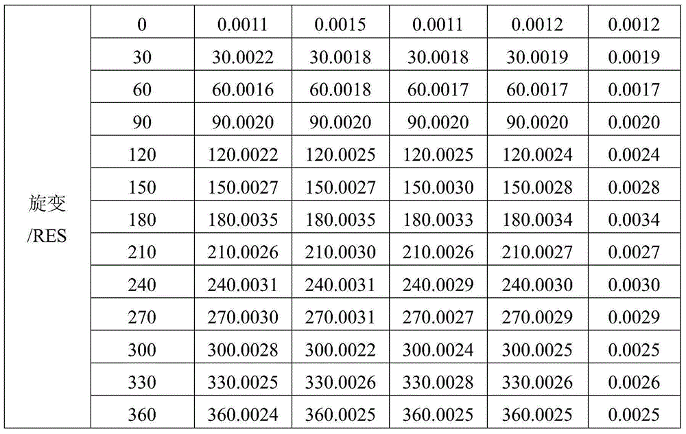
[0061] After power on, according to the use requirements of the calibrated synchronous transmitter 1328 / 1TE, use the special power supply system a...


PUM


Abstract

The invention relates to an onsite calibration method for a synchro transmitter or analyzer, and particularly aims to meet the calibration requirement of the synchro transmitter or analyzer which is difficult to detach from large-scale equipment. The field calibration method comprises the following steps: adopting a special power system used for supplying power to onboard experimental equipment on an experiment or work site to provide a reference signal; based on the characteristics that an angular position indicator can be used for directly measuring a vector angle and is portable, taking the angular position indicator, which is certificated or calibrated by a supervising authority, and has an accuracy class three times or higher than (or has the same magnitude order as) the synchro transmitter or analyzer to be calibrated, as standard equipment for calibration, directly measuring an output angle value of the synchro transmitter or analyzer to be calibrated on the experiment or work site, and calculating an error and uncertainty to obtain complete and accurate calibration data. Through the adoption of the onsite calibration method, the synchro transmitter or analyzer can be calibrated on site.

Description

technical field [0001] The invention relates to a method for realizing on-site calibration of a synchronous transmitter / resolver, and is especially suitable for the calibration requirement of a synchronous transmitter / resolver that is difficult to disassemble on large equipment. Background technique [0002] To calibrate synchronous transmitter / resolver and other types of equipment, the general application method is to give a reference signal through a variable frequency power supply or a power signal source (Valiable Signal Source), use a special bridge (Resolver-Synchro Bridge) and a digital multimeter or phase Phase Angle Voltmeter (Phase Angle Voltmeter) calibrates the measurement error of the voltage or angle value output by the synchronous transmitter / resolver. Although the above method has high calibration accuracy, it has relatively high requirements on the calibration environment and standards. It is generally only suitable for synchronization / analysis equipment wit...

Claims


Application Information

Patent Timeline
IPC IPC(8): G01R35/00
Inventor 侯秀波何俊芳徐庆玉衣广华
Owner HARBIN
Why Eureka
Try Eureka