Panoramic camera and PTZ camera combined control method and panoramic camera and PTZ camera combined control device

A panoramic camera and video camera technology, applied in image communication, TV, color TV parts, etc., can solve the problems of poor detail image acquisition ability and resolution limitation in local areas of omnidirectional space

Inactive Publication Date: 2010-05-12
PUWELL TECH
View PDF0 Cites 69 Cited by
  • Summary
  • Abstract
  • Description
  • Claims
  • Application Information

AI Technical Summary

Problems solved by technology

[0003] The inventor found through research on the prior art that the existing panoramic camera can solve the function of panoramic monitoring of a certain omnidirectional space, but limited by the resolution of the camera, the detailed image of the local area of ​​the omnidirectional space Relatively poor ability to obtain

Method used


Image

  • Panoramic camera and PTZ camera combined control method and panoramic camera and PTZ camera combined control device
  • Panoramic camera and PTZ camera combined control method and panoramic camera and PTZ camera combined control device
  • Panoramic camera and PTZ camera combined control method and panoramic camera and PTZ camera combined control device

Examples


Embodiment Construction

[0052] The embodiment of the present invention discloses a method and device for the linkage control of a panoramic camera and a PTZ camera. In order to make the objectives, technical solutions, and advantages of the present invention clearer, the present invention will be further described in detail with reference to the accompanying drawings and embodiments.

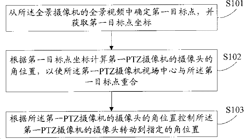
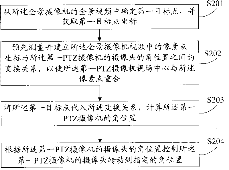
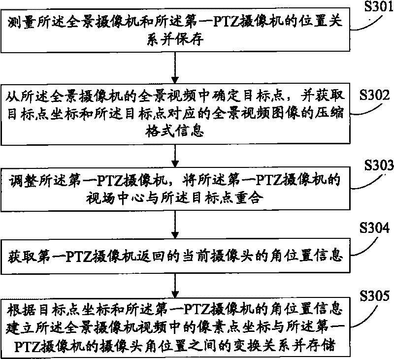
[0053] The panoramic camera can realize the function of panoramic monitoring of a certain omnidirectional space, that is, the whole situation of a certain omnidirectional space can be seen in the video of the panoramic camera. However, due to the characteristics of the panoramic camera itself, the field of view is too large, and the limited pixel resolution of the camera will reduce the resolution of the details of the panoramic camera. It may not be possible to carefully view a certain point in the panoramic camera video. To solve this problem, see figure 1 , The method provided by the embodiment of the present invention ...


PUM


Abstract

The embodiment of the invention discloses a panoramic camera and PTZ camera combined control method and a panoramic camera and PTZ camera combined control device. Although the traditional panoramic camera has a function of panoramically monitoring certain omnidirectional space, but has a relatively lower capability for acquiring detailed images in a local region in the panoramic space due to the limitation of the resolution of the camera. The embodiment of the invention adopts a technical scheme that: a panoramic camera and PTZ cameras are combined; after a first target point in a video of the panoramic camera is determined, the angular position of a first PTZ camera is computed by using the coordinate of the first target point and the camera of the first PTZ camera is adjusted according to the angular position to allow the first target point to be displayed in the center of the view field of the PTZ camera; and based on the self properties of the PTZ cameras, the region taking the first target point as a center is displayed in a more detailed way to an image with higher resolution.

Description

Technical field [0001] The present invention relates to the technical field of video surveillance, in particular to a method and device for linkage control of a panoramic camera and a PTZ camera. Background technique [0002] The current panoramic camera adopts a special imaging system, which can realize 360-degree monitoring without blind spots in a large space. [0003] The inventor found through research on the prior art that the existing panoramic camera can solve the function of panoramic monitoring of a certain omnidirectional space, but limited by the camera resolution, the detailed image of the local area of ​​the omnidirectional space is limited. The ability to acquire is relatively poor. Summary of the invention [0004] In view of this, the purpose of the embodiments of the present invention is to provide a method and device for linkage control of a panoramic camera and a PTZ camera, which uses the panoramic camera to monitor the panorama, and at the same time obtains th...

Claims


Application Information

Patent Timeline
Patent Type & Authority Applications(China)
IPC IPC(8): H04N5/232H04N5/225H04N7/18
Inventor 李必勇李捷
Owner PUWELL TECH
Why Eureka
Try Eureka