Locking device for scissor-type hydraulic lifting platform
A technology of hydraulic lifting platform and locking device, which is applied in the direction of lifting device, lifting frame, transmission device, etc., and can solve the problem of not being able to self-lock for a long time
- Summary
- Abstract
- Description
- Claims
- Application Information
AI Technical Summary
Problems solved by technology
Method used
Image
Examples
Embodiment Construction
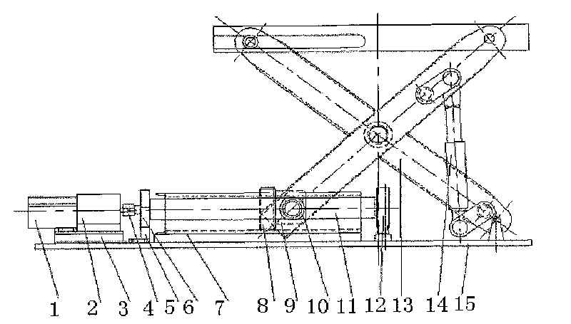
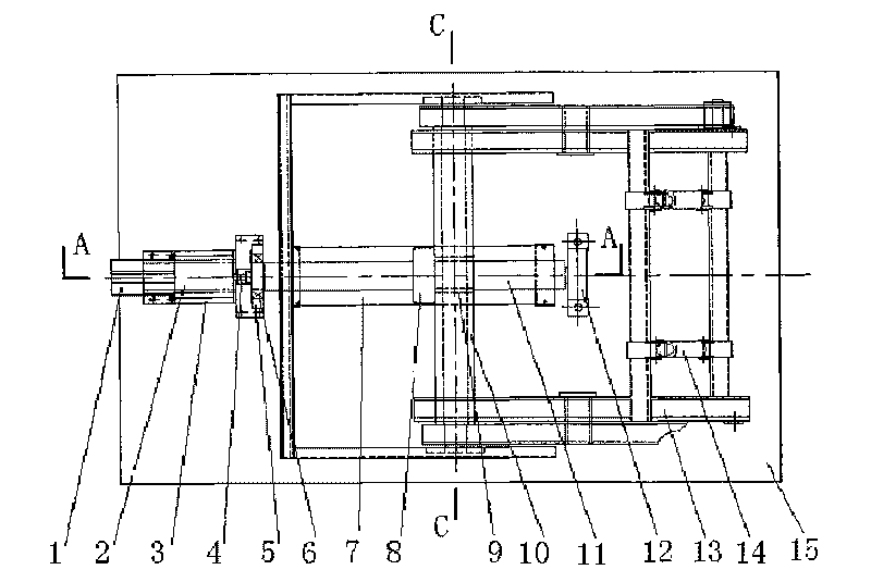
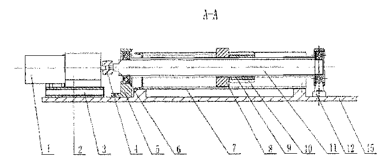
[0026] This embodiment includes a hydraulic motor 1, a reducer 2, a lead screw 11, a lock nut 8 and a connecting rod shaft system.
[0027] Such as figure 1 , figure 2 , image 3 , Figure 4 shown. The hydraulic motor 1 is directly connected to the reducer 2, and the reducer 2 is installed on the driving base 3 with bolts, and the driving base 3 is fixed on one end of the platform 15 at the bottom of the elevating support by bolts. The reducer 2 is connected to the lead screw 11 through the coupling 4; the middle part of the lead screw 11 passes through the connecting rod shaft 10 of the lifting bracket 13 through the lead screw guide sleeve 9; the square lock nut 8 is set on the lead screw 11 and is located on One side of the connecting rod shaft 10. The square lock nut 8 is placed on the flat plate 7; the flat plate 7 is fixed on the platform 15 of the lifting bracket by screws. When the lead screw 11 rotates and drives the lock nut 8 to rotate accordingly, due to the...
PUM
 Abstract
Description
Claims
Application Information
 - R&D
- Intellectual Property
- Life Sciences
- Materials
- Tech Scout
- Unparalleled Data Quality
- Higher Quality Content
- 60% Fewer Hallucinations
Browse by: Latest US Patents, China's latest patents, Technical Efficacy Thesaurus, Application Domain, Technology Topic, Popular Technical Reports.
© 2025 PatSnap. All rights reserved.Legal|Privacy policy|Modern Slavery Act Transparency Statement|Sitemap|About US| Contact US: help@patsnap.com


