
A filter membrane clamping device with self-locking shock-absorbing function

A clamping device and filter membrane technology, which is applied in the fields of dispersed particle filtration, dispersed particle separation, chemical instruments and methods, etc. It can solve the problems of poor stability and shock absorption, large overall weight and volume, and no shock absorption function, etc. problem, to achieve the effect of preventing movement and falling off, low production cost, and good shock absorption effect

Active Publication Date: 2017-09-01
QINGDAO ZHONGRUI INTELLIGENT INSTR
View PDF5 Cites 0 Cited by
  • Summary
  • Abstract
  • Description
  • Claims
  • Application Information

AI Technical Summary

Problems solved by technology

[0003] There are many kinds of filter clamping devices on the market, but their common disadvantage is that the stability and shock absorption effect are not good.
Some have shock-absorbing function, but they can’t realize the smooth operation of the whole process, so it will still cause the vibration of the filter membrane and affect the accuracy of the experiment; although some can prevent the filter membrane from falling off, but the structure is bulky, the overall weight and volume are relatively large, which affects the overall portability Although some structures are simple, they have no shock-absorbing function, and it is easy to cause the filter membrane to fall off, which makes the experiment invalid

Method used


Image

  • A filter membrane clamping device with self-locking shock-absorbing function

Examples


Embodiment Construction

[0024] Below in conjunction with accompanying drawing, structural composition and working principle of the present invention are described as follows:

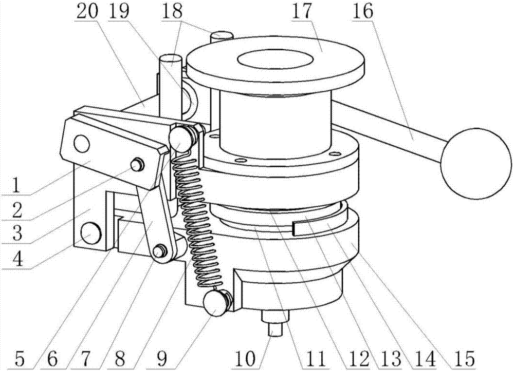
[0025] Such as figure 1 As shown, a filter membrane clamping device with self-locking damping function includes: crank 1, crank shaft 2, fixed seat 3, rocker shaft 4, spring upper hook 5, connecting rod 6, connecting rod shaft 7, spring 8 , spring lower hook 9, air extraction nozzle 10, lower sealing ring 11, upper sealing ring 12, filter membrane 13, limit seat 14, rocker 15, handle 16, air intake seat 17, damper 18, bearing 19, main Revolving shaft 20. The crank 1 and the handle 16 are rigidly connected with the main shaft 20, so that the swing handle 16 can drive the main shaft 20 to rotate, thereby driving the crank 1 to swing; The rod 6 rotates around the crank shaft 2, and the overlapping part of the crank 1 and the connecting rod 6 has a limit groove to ensure that the connecting rod 6 cannot continue to rotate after ...


PUM


Abstract

The invention discloses a filter membrane clamping device with a self-locking damping function. A handle, a main rotary shaft and a crank are rigidly and integrally connected; the outer end part of the crank is connected with one end of a connecting rod through a crank rotary shaft, and a limiting groove is formed in the coinciding part of the crank and the connecting rod; the other end of the connecting rod is connected with a rocker rod through a connecting rod rotary shaft, and the connecting rod rotary shaft is fixedly arranged on the rocker rod; the rocker rod is connected with a fixing seat through a rocker rod rotary shaft, and the main rotary shaft is connected with a fixing seat through a bearing; the upper end and lower end of the spring are respectively connected with a spring upper hook and a spring lower hook of the fixing seat; the bottom part of a damper which is arranged on the fixing seat is in contact with the rocker rod; a filter membrane is in sealed connection with the rocker rod and the fixing seat respectively through a lower sealing ring and an upper sealing ring, and a limiting seat is arranged on the rocker rod; the fixing seat is in sealed connection with an air intake seat, and an air suction nozzle is matched with an air suction system. The filter membrane clamping device has the advantages that the mechanical self-locking function is realized, the clamping speed is high, the movement is stable, the damping effect is good, the movement and falling of the filter membrane are prevented, the whole structure is simple and compact, the cost is low, and the portability is good.

Description

technical field [0001] The invention belongs to the technical field of filter membrane clamping equipment, and in particular relates to a filter membrane clamping device with a self-locking shock-absorbing function. Background technique [0002] Particles in ambient air or exhaust gas from pollution sources often need to be captured by membrane filtration. When measuring, the air inlet is connected to the air source, and the air outlet is connected to the sensor. The gas to be measured in the air source enters the inlet through the air inlet. In the gas cavity, after being filtered by the filter membrane, it enters the sensor through the gas outlet cavity and the gas outlet, and the sensor detects the gas, and continuous experiments are required during operation, which requires the replacement of the filter membrane between each experiment. When the filter membrane method collects particulate matter, the particulate matter is attached to the surface of the filter membrane, s...

Claims


Application Information

Patent Timeline
Patent Type & Authority Patents(China)
IPC IPC(8): B01D46/42
CPCB01D46/0005B01D46/4227
Inventor 郭亮刘涛王鹏迟方圆徐立佳
Owner QINGDAO ZHONGRUI INTELLIGENT INSTR
Learn More