Push type power socket

A power socket and push-type technology, which is applied in the direction of circuits, electrical components, and devices to prevent contact with live contacts, can solve problems such as laborious plugging and unplugging, accidents, and failure to eliminate power sockets, so as to avoid accidental touch and increase safety. Effect

Inactive Publication Date: 2010-05-26
陈琦文
View PDF0 Cites 28 Cited by
  • Summary
  • Abstract
  • Description
  • Claims
  • Application Information

AI Technical Summary

Problems solved by technology

If the socket 1 is not fixed on the wall or on the table, but placed on the ground or on the table, the user must press the socket 1 with one hand to pull out the plug 2 with the other hand. The structure brings the disadvantage of inconvenient use
[0004] In addition, the conductive clip 11 of the existing power socket 1 is in a state of continuously maintaining power supply, and it is easy for children to use tools to insert into the socket 12 of the power socket and cause accidents, which poses a safety hazard
[0005] Most of the sockets that have been improved based on safety considerations in the past are provided with push button switches to start or turn off the power supply, or safety devices are provided at the front and back of the socket to avoid accidental touch, but this will increase the inconvenience in use, and still does not eliminate the existing above-mentioned sockets. The defect that the power socket needs to be plugged in and out

Method used


Image

  • Push type power socket
  • Push type power socket
  • Push type power socket

Examples


Embodiment Construction

[0032] The specific implementation manners of the present invention will be further described in detail below in conjunction with the accompanying drawings.

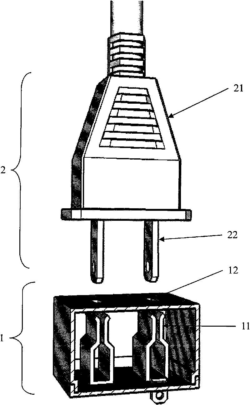
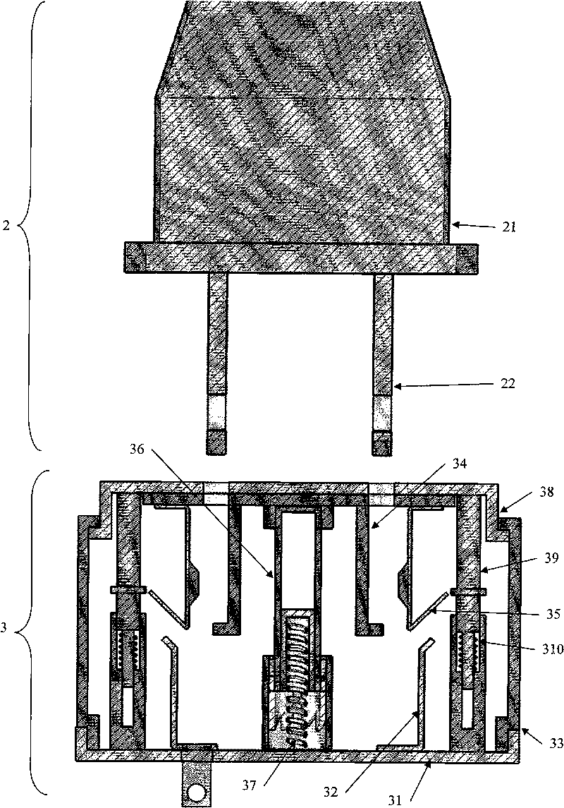
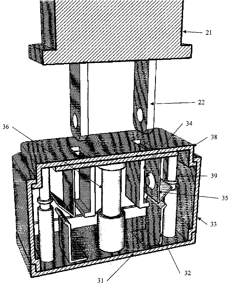
[0033] Figure 2-Figure 6 It is the first embodiment of the present invention. Such as figure 2 , image 3 , Figure 4 As shown, the power socket of the present embodiment has a base 31, two conductive sheets 32 fixed on the base, a side cover 33, a movable frame 34, two conductive clips 35 fixed on the movable frame, a two-section The button structure 36 of the type is fixed between the base and the movable frame. This two-stage button structure is similar to the two-stage button on the general ballpoint pen. After pressing it once and letting go, it can maintain the pressed state. will return to its original state.

[0034] Such as Figure 5 As shown, when the user inserts the conductive blade 22 of the plug 2 into the power socket 3, the user exerts force on the plug base 21, and the conductive blade 22 of the ...


PUM


Abstract

The invention discloses a push type power socket. In order to solve the problems that the traditional power socket wastes labor when being used, is inconvenient and has potential safety hazards, the push type power socket is designed. The push type power socket comprises a substrate, at least two conducting strips, a two-section button structure, an upper cover, a movable frame and at least two conducting clamps, wherein the conducting strips are arranged on the substrate; one ends of the conducting strips are used for being connected to a power supply, and the other ends are used for being connected with the conducting clamps; the two-section button structure is arranged on the substrate; the upper cover is provided with at least two jacks which are used for being inserted by conducting inserted sheets of plugs; the movable frame is connected on the two-section button structure, directly or indirectly bear the push of the plugs to move and presses the two-section button structure; the conducting clamps bear the push of the movable frame to be connected with the conducting strips on the substrate to clamp the conducting inserted sheets of the plugs, and the movable frame returns to the in-situ state; and the conducting clamps return to the in-situ state simultaneously to loose the conducting inserted sheets of the plugs and separate the conducting strips on the substrate. The invention is suitable for serving as various types of power sockets of two-jack power sockets, three-jack power sockets, USS power sockets, EN power sockets, independent power sockets, in-wall type power sockets and the like.

Description

technical field [0001] The invention relates to a power socket, in particular to a push-type power socket. Background technique [0002] Such as figure 1 As shown, the existing power socket 1 is provided with at least two conductive clips 11 . When using the socket 1, you must hold the base 21 of the plug 2 and insert the conductive insert 22 into the jack 12 of the socket 1, and then the user must forcefully overcome the elastic stress and friction of the conductive clip 11 of the socket 1 to make the plug The conductive insert 22 of 2 is inserted into the conductive clip 11 of the socket 1. [0003] When the plug 2 is to be pulled out, the user holds the base 21 of the plug 2 and overcomes the friction force of the conductive clip 11 of the socket 1 with force, so that the plug 2 can be pulled out. If the socket 1 is not fixed on the wall or on the table, but placed on the ground or on the table, the user must press the socket 1 with one hand to pull out the plug 2 with...

Claims


Application Information

Patent Timeline
Patent Type & Authority Applications(China)
IPC IPC(8): H01R13/71H01R13/15H01R13/635H01R13/44
Inventor 陈琦文
Owner 陈琦文
Why Eureka
Try Eureka