
Oiltight structure of motor shaft tube

A technology of preventing oil leakage and motor shaft, which is applied in the direction of casing/housing/support, controlling mechanical energy, electrical components, etc. It can solve the problem of reducing the viscosity of lubricating oil, prolonging the leakage path of lubricating oil, and easy leakage of lubricating oil, etc. problem, to achieve the effect of preventing the loss of lubricating oil

Active Publication Date: 2010-05-26
SUNONWEALTH ELECTRIC MACHINE IND
View PDF0 Cites 3 Cited by
  • Summary
  • Abstract
  • Description
  • Claims
  • Application Information

AI Technical Summary

Problems solved by technology

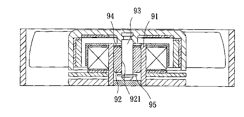
[0003] When the rotating shaft 93 rotates in the shaft hole 921 of the bearing 92, the temperature generated by friction will reduce the viscosity of the lubricating oil, making the lubricating oil easier to leak
Although the bearing 92 top surface of existing structure is provided with a gasket 94 in order to block lubricating oil, yet, this lubricating oil still can leak from the gap of this bearing and rotating shaft and the gap of this bearing and shaft tube, and this gasket The gap between 94 and the shaft tube 91 is relatively extended from the gap between the bearing 92 and the shaft tube 91, so when lubricating oil leaks from the gap between the bearing 92 and the shaft tube 91 to the gasket 94, the setting of the gasket 94 is only The leakage path of the lubricating oil is extended, so the loss rate of the lubricating oil can only be slightly delayed

Method used


Image

  • Oiltight structure of motor shaft tube
  • Oiltight structure of motor shaft tube
  • Oiltight structure of motor shaft tube

Examples


Embodiment Construction

[0021] In order to make the above-mentioned and other objects, features and advantages of the present invention more comprehensible, the preferred embodiments of the present invention are specifically cited below, together with the accompanying drawings, and are described in detail as follows:

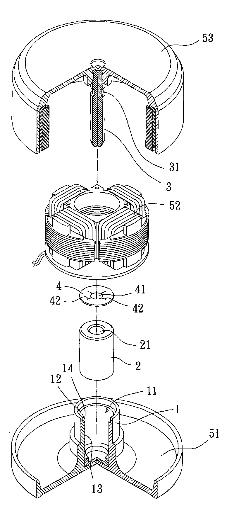
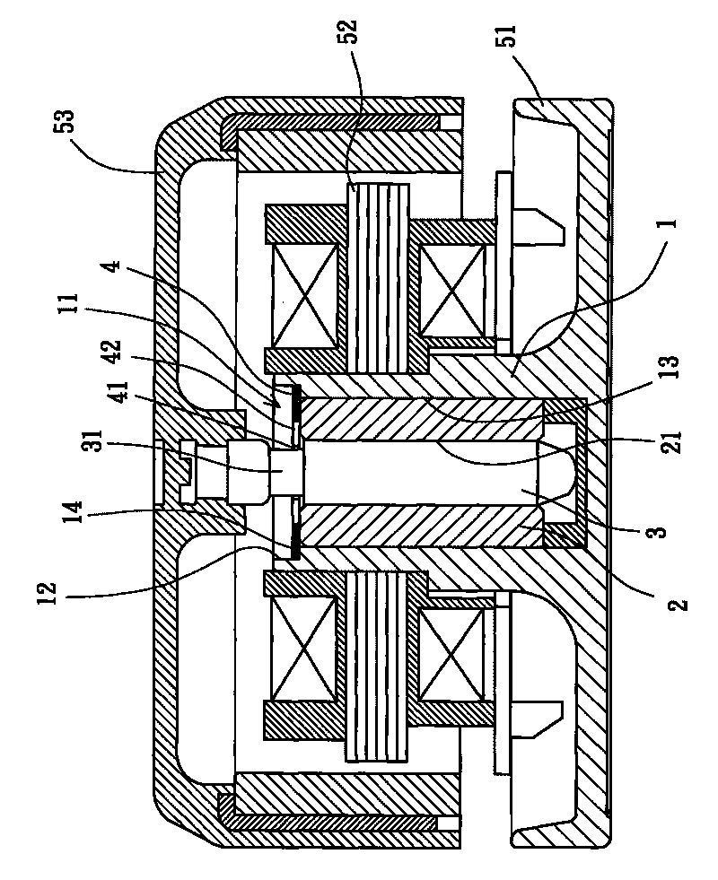
[0022] refer to figure 2 and 3 As shown, the anti-leakage structure of the motor shaft tube in the first embodiment of the present invention includes a shaft tube 1 , a bearing 2 , a rotating shaft 3 and a leak-proof sheet 4 .

[0023] The shaft tube 1 is disposed on a base 51 , and the base 51 can also be provided with a stator 52 . Wherein, the shaft tube 1 and the base 51 may be integrally formed as a single body, or may be composed of separate shaft tube 1 and base 51 (not shown). The shaft tube 1 has an inner hole 11 inside. One end of the inner hole 11 is a closed blind hole, and the end of the inner hole 11 is preferably closed with the base 51 . The inner hole 11 has a larg...


PUM


Abstract

The invention relates to an oiltight structure of a motor shaft tube, comprising a shaft tube, a bearing, a rotating shaft and a leakproof sheet. The shaft tube is provided with an inner hole which is provided with a large diameter part and a small diameter part; the large diameter part is arranged at one end of the inner hole, the other end of the inner hole is a closed blind hole; the bearing is arranged at the small diameter part and provided with a shaft hole in the center; the rotating shaft is articulated with the shaft hole of the bearing and provided with a reduced diameter part on the periphery surface; the leakproof sheet is fixedly arranged on the large diameter part and provided with a limit hole in the center; and the peritreme of the limit hole is embedded in the reduced diameter part of the rotating shaft. Accordingly, the invention can utilize the leakproof sheet to block the leakage path of lubricating oil and can prevent the rotating shaft from axially moving or loosening, thereby simplifying the spare parts of the motor.

Description

technical field [0001] The invention relates to a motor shaft tube structure, in particular to an oil leakage prevention structure of the motor shaft tube to prevent lubricating oil in the shaft tube from losing. Background technique [0002] refer to figure 1 As shown, the conventional motor has a shaft tube 91 for accommodating a bearing 92 , and a shaft hole 921 is provided in the center of the bearing 92 . The motor also has a rotating shaft 93 . One end of the rotating shaft 93 is combined with the rotor of the motor, and the other end is rotatably pivoted in the shaft hole 921 of the bearing 92 . The top surface of the bearing 92 is provided with an annular gasket 94 in order to block the way of lubricating oil leakage, and the end of the rotating shaft 93 passing through the shaft hole 921 is provided with a holding element 95, by which the holding element 95 is buckled and fixed on the end of the rotating shaft 93 to prevent the rotating shaft 93 from being axially...

Claims


Application Information

Patent Timeline
Patent Type & Authority Applications(China)
IPC IPC(8): H02K5/167H02K7/08
Inventor 洪银树
Owner SUNONWEALTH ELECTRIC MACHINE IND
Learn More