Pipelaying vessel

A pipeline and pipeline technology, applied in the field of pipeline laying ships, can solve problems such as limited accuracy, and achieve the effect of easy installation and disassembly

Active Publication Date: 2010-05-26
ITREC BV
View PDF2 Cites 22 Cited by
  • Summary
  • Abstract
  • Description
  • Claims
  • Application Information

AI Technical Summary

Problems solved by technology

However, this system has the disadvantage of limited accuracy

Method used


Image

  • Pipelaying vessel
  • Pipelaying vessel
  • Pipelaying vessel

Examples


Embodiment Construction

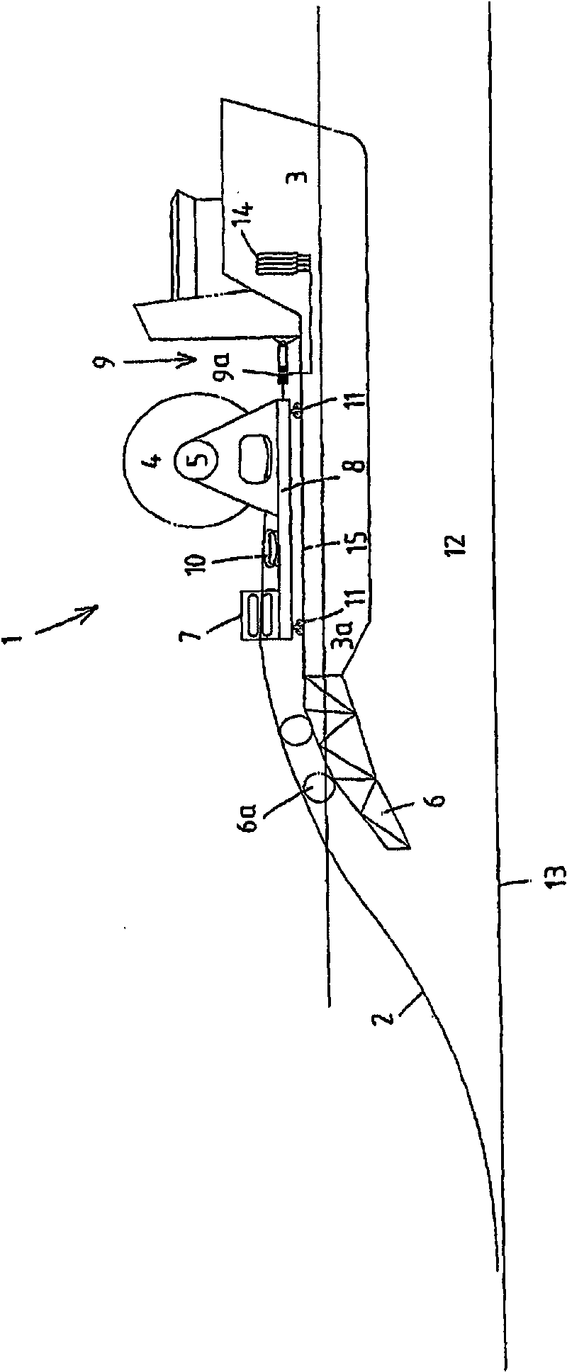
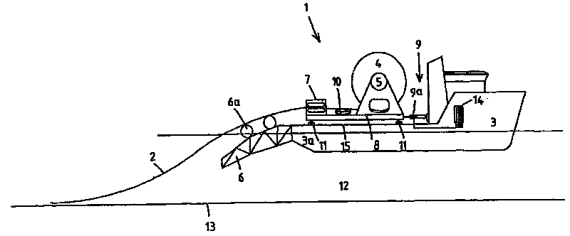
[0021] exist figure 1 A device 1 according to the invention is shown in FIG. 2 for the continuous laying of a pipeline 2 from a pipe-laying vessel 3 into a body of water 12 .

[0022] It should be appreciated that vessel 3 need not be a dedicated pipelaying vessel. Indeed, it is contemplated that the vessel 3 may be an offshore supply vessel (OSV), as described herein, with an open deck 15 at the rear of the vessel.

[0023] In the present example, the device 1 comprises a cylindrical reel 4 having a horizontally extending axis 5 perpendicular to the longitudinal direction of the pipeline 2 to be laid. The pipeline 2 to be laid is wound on a reel 4 .

[0024] The stern stinger 6 is mounted at the stern part 3 a of the vessel 3 and guides the pipeline 2 along a curved path during its lowering into the body of water 12 onto the base 13 of the body of water.

[0025] In the embodiment shown, the stern stinger 6 includes rollers 6a (exaggerated in the figure) for supporting and...


PUM


Abstract

The present invention relates to an apparatus for continuously laying a pipeline on the floor of a body of water from a pipelaying vessel, said apparatus comprising: a generally cylindrical reel with an axis upon which the pipeline is wound, a stinger provided at the stern of the vessel for guiding the lowered pipeline, launch means for the controlled lowering of the pipeline over the stinger of said vessel and into the body of water. This apparatus further comprises a frame supporting the reel and the launch means, adapted to be moveable with respect to the vessel in the longitudinal direction of the pipeline, and a tension device to be mounted between the frame and the vessel, adapted to control the pipeline tension in a predetermined tension range during pipelaying.

Description

technical field [0001] The invention relates to an apparatus for the continuous laying of pipelines from a pipe-laying vessel onto the substrate of a body of water. The equipment includes a reel on which the pipeline to be laid is wound. The apparatus also includes a stern stinger or other curved passage pipeline guiding means such as curved rails, wheels or chutes arranged at the stern of the ship for guiding the lowered pipeline. The apparatus also includes launching means for lowering the control line over the stern bracket tube of the vessel into the body of water. Background technique [0002] Such a boat is known for example from US3965713. It provides a reel with a substantially vertical axis and the launching means in this embodiment are formed by stretching means. During the pipeline laying process, it is important to control the tension of the pipeline within the predetermined tension range. There is a risk of excessive stress (too much tension in the pipe) or ...

Claims


Application Information

Patent Timeline
Patent Type & Authority Applications(China)
IPC IPC(8): B63B35/03F16L1/16
CPCF16L1/203F16L1/18B63B35/03
Inventor A·别列兹尼茨基J·罗登伯格
Owner ITREC BV
Why Eureka
Try Eureka