Permanent magnet synchronous motor control method and system based on encoder automatic zero set

A permanent magnet synchronous motor and control method technology, applied in the direction of motor generator control, control system, vector control system, etc., can solve the problems of poor robustness, high requirements for hardware equipment, and high requirements for the accuracy of current detection equipment, and achieve the process Convenience, high precision, and the effect of avoiding the phenomenon of rotor oscillation back and forth

Active Publication Date: 2013-08-28
ZHEJIANG UNIV
View PDF3 Cites 58 Cited by
  • Summary
  • Abstract
  • Description
  • Claims
  • Application Information

AI Technical Summary

Problems solved by technology

[0005] Although the back EMF detection method does not need to add additional equipment, its robustness is poor, and the accuracy of the current detection equipment is high. What is more fatal is that the rotor position of the motor cannot be accurately obtained under low-speed and zero-speed operation.
[0006] Yan Shuai et al. pointed out the application of high-frequency signal injection method in the literature titled Permanent Magnet AC Servo System and Its Advanced Control Strategy (Harbin Institute of Technology Doctoral Dissertation, pp.11-12, April 2009), which solved the problem of The problem of rotor position detection at low speed, but not only the hardware requirements are high when detecting signals, but also band-pass filters and synchronous shafting high-pass filters are used in signal processing, which will introduce a certain time lag and phase lag , cannot well meet the control requirements of high-precision SVPWM (Space Vector Pulse Width Modulation), and at the same time, the injected high-frequency signal will introduce relatively large noise during operation

Method used


Image

  • Permanent magnet synchronous motor control method and system based on encoder automatic zero set
  • Permanent magnet synchronous motor control method and system based on encoder automatic zero set
  • Permanent magnet synchronous motor control method and system based on encoder automatic zero set

Examples


Embodiment Construction

[0056] In order to describe the present invention more specifically, the technical solutions and working principles of the present invention will be described in detail below in conjunction with the accompanying drawings and specific embodiments.

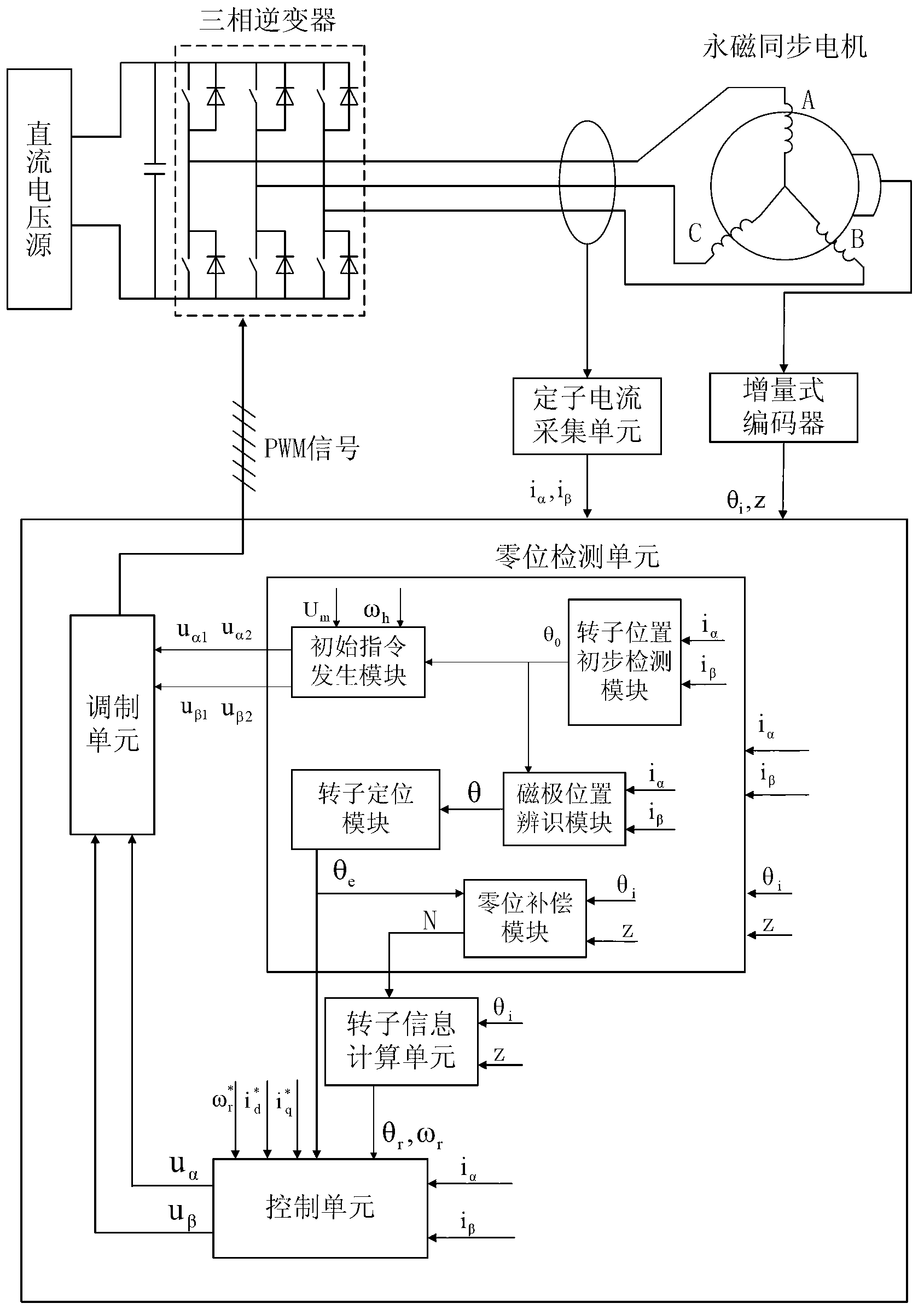
[0057] The control object of this embodiment is a permanent magnet synchronous motor system, which includes a DC voltage source, a three-phase inverter and a permanent magnet synchronous motor; it is powered by a DC voltage source, and the output terminal of the DC voltage source is connected in parallel with a stabilizing capacitor through three A phase inverter converts direct current into alternating current and is connected to the stator input of the permanent magnet synchronous motor. The three-phase inverter is composed of a power switch tube and a freewheeling diode. Some power switch tubes contain a freewheeling diode, so the independent freewheeling diode can be omitted and the built-in freewheeling diode can be used.

[00...


PUM


Abstract

The invention discloses a permanent magnet synchronous motor control method based on encoder automatic zero set. An improved high-frequency voltage injection method is used for detecting the initial position of a rotor, the initial position of the rotor is clear, voltage vectors can be applied conveniently, and a motor rotor reverse rotating phenomenon is avoided. Meanwhile, encoder zero compensation is carried out automatically, a compensation value is stored, direct calling in the future is convenient, and trouble of manual zero set is removed. Once calibration or zero reset is needed, operation through the method is carried out for one time, an encoder is subjected to accurate zero set again, a process is simple, and accuracy is high. The invention further discloses a control system which achieves the control method. After the initial position of the rotor is obtained through a rotor locating module, a voltage vector closest to the position is chosen to be applied, so that a rotor back-and-forth vibration phenomenon during locating is avoided, a high-frequency voltage signal is injected only before the rotor is located initially, phase lag and time lag cannot be brought to system operation, and noise cannot be introduced during operation.

Description

technical field [0001] The invention belongs to the technical field of motor control, and in particular relates to a permanent magnet synchronous motor control method and system based on encoder automatic zero adjustment. Background technique [0002] With the rapid development of science and technology, servo control systems have been widely used in many high-tech fields, such as robot control, CNC machine tools, large-scale integrated circuit manufacturing, office automation, flexible manufacturing systems, aerospace, radar and various military Weapon follow system, etc. At present, most servo systems on the market use permanent magnet synchronous motors, and to achieve high-precision control of high-performance permanent magnet synchronous servo systems, it is necessary to obtain rotor position signals at all times. The main methods of existing permanent magnet synchronous servo motor rotor position detection can be divided into two categories: mechanical position sensor...

Claims


Application Information

Patent Timeline
Patent Type & Authority Applications(China)
IPC IPC(8): H02P21/14H02P25/02H02P27/08H02P21/18
Inventor 沈建新何磊杰缪冬敏
Owner ZHEJIANG UNIV
Why Eureka
Try Eureka