Hoisting rigging device
A technology for hoisting ropes and rigging, applied in the directions of transportation and packaging, load hoisting components, etc., can solve the problems of low work efficiency, unsolved problems, wire rope damage, etc., to achieve safe work load, overcome unsafe rigging, Not easy to damage effect
Inactive Publication Date: 2010-06-02
广州建峰钢绳索具有限公司
View PDF6 Cites 6 Cited by
- Summary
- Abstract
- Description
- Claims
- Application Information
AI Technical Summary
Problems solved by technology
Due to the high surface temperature of the aluminum rod after casting, the steel wire rope will be in direct contact with the casting rod during the hoisting process, so the steel wire rope will be damaged quickly, and the work efficiency is very low, especially the casting rod is lifted from the mold and then turned over and falls. Work injuries and accidents often occur when placed flat on the ground
However, this situation has not been resolved
Method used
View moreImage
Smart ImageViewing Examples
Examples
Embodiment 2
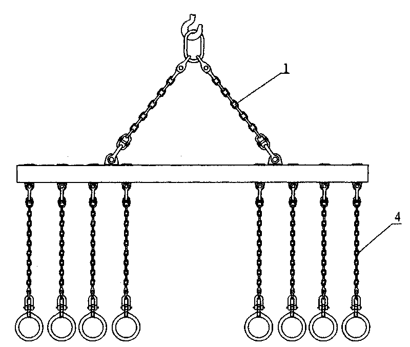
[0036] As described in Embodiment 1, the difference between the hoisting rigging device provided in this embodiment and the hoisting rigging device provided in Embodiment 1 is that: wherein the main rigging 1 and / or vertical rigging 4 of two limbs adopt chains (such as image 3 shown).
Login to View More PUM
 Abstract
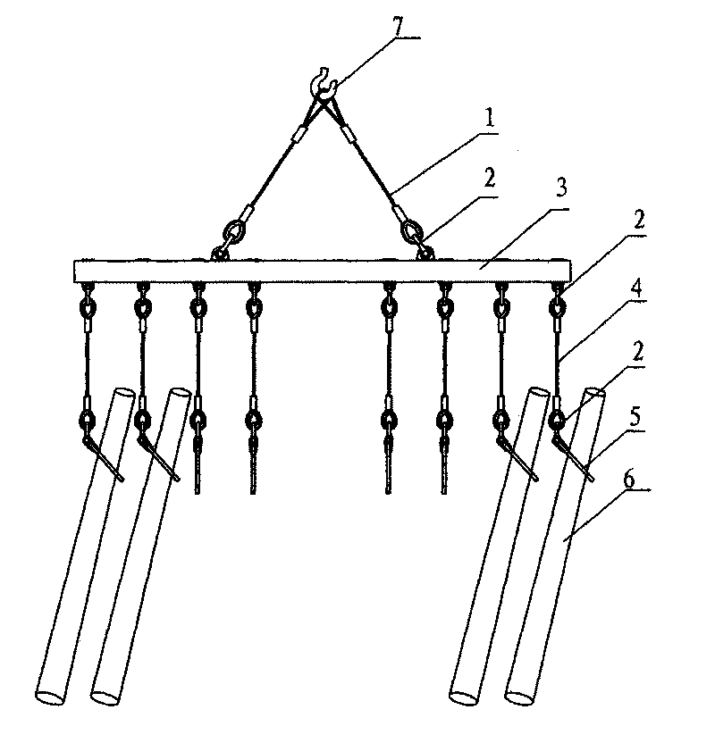
The invention discloses a hoisting rigging device. The device comprises a main supporting bar, a rigging and a locking device which is used for locking a hoisted object, wherein the rigging comprises a two-limb main rigging and a vertical rigging; the upper end of the main supporting bar is connected with the two-limb main rigging; the lower end of the main supporting bar is provided with at least one vertical rigging; the locking device is arranged under the vertical rigging and moveably connected with the vertical rigging. The hoisting rigging device provided by the invention ensures that workers easily take a cast rod out of a mould, hoist and turn over the cat rod, and put the cast rod on the ground, and the hoisting rigging device can be provided with a plurality of riggings at the same time, which greatly improves the working efficiency; moreover, the hoisting rigging device is characterized by safety and reliability, simple structure, and convenient operation.
Description
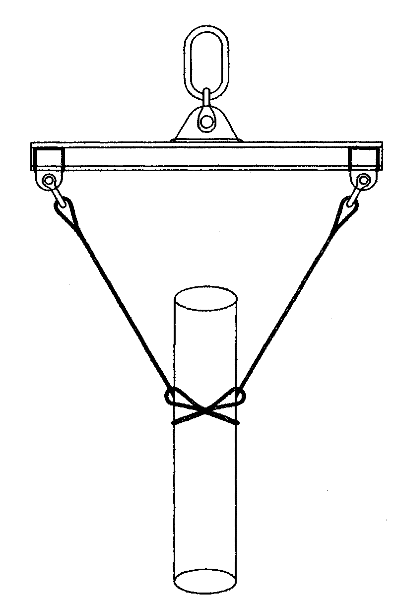
technical field [0001] The invention relates to a hoisting rigging device. Background technique [0002] For factories that produce aluminum alloy extrusion profiles, the raw materials for extruding aluminum alloy doors, windows and profiles are all aluminum alloy cast rods that are cast and melted by aluminum alloy, and then machined into extruded rods of various specifications and sizes. The process of casting rods is to place the casting mold below the ground level of the foundry, and cast into rods of the required size, diameter and length at one time. But after the casting process is finished, it is a very difficult and very unsafe work to take out the cast rod. Due to the large size of the cast rod series, the generally larger diameter and length of the cast rod, such as The cast rod weighs about 3 tons, so it is very difficult to lift the cast rod. Generally be to adopt welded I-beam rigging in the prior art (see Figure 1 ), use wire rope inserting slings and rol...
Claims
Login to View More Application Information
Patent Timeline
 IPC IPC(8): B66C1/12
Inventor 胡耀东
Owner 广州建峰钢绳索具有限公司
- R&D Engineer
- R&D Manager
- IP Professional
Why Eureka
- Industry Leading Data Capabilities
- Powerful AI technology
- Patent DNA Extraction
Eureka Blog
Learn More Browse by: Latest US Patents, China's latest patents, Technical Efficacy Thesaurus, Application Domain, Technology Topic, Popular Technical Reports.
© 2024 PatSnap. All rights reserved.Legal|Privacy policy|Modern Slavery Act Transparency Statement|Sitemap|About US| Contact US: help@patsnap.com


