
Touch-control display panel and touch-control base plate

A touch display panel, panel technology, applied in the direction of instruments, electrical digital data processing, data processing input/output process, etc., can solve the problem of insufficient area, the inability to increase the touch substrate 100, and the inability to increase the side width W of the touch substrate 100 Minimize and other issues, to achieve the effect of increasing the use of area

Active Publication Date: 2011-06-15
AU OPTRONICS CORP
View PDF0 Cites 3 Cited by
  • Summary
  • Abstract
  • Description
  • Claims
  • Application Information

AI Technical Summary

Problems solved by technology

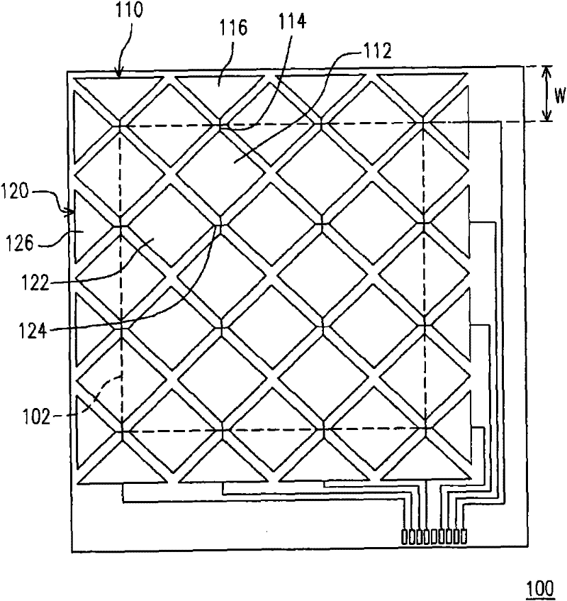
However, the area of ​​the first edge electrode 116 and the second edge electrode 126 is insufficient, which cannot be used for touch sensing and cannot increase the area of ​​the active region 102 of the touch substrate 100
In other words, the side width W of the touch substrate 100 still cannot be reduced

Method used


Image

  • Touch-control display panel and touch-control base plate
  • Touch-control display panel and touch-control base plate
  • Touch-control display panel and touch-control base plate

Examples


Embodiment Construction

[0077] Figure 2A ~ Figure 2C They are respectively a touch substrate and two touch display panels according to an embodiment of the present invention. Please refer to Figure 2A The touch substrate 200A includes an auxiliary substrate 202 and a touch element 210 disposed on the auxiliary substrate 202 . Figure 2B The design of the middle touch display panel 200B is to attach the above-mentioned touch substrate 200A to the flat display panel 206 through an adhesive layer 204 . The flat display panel 206 is composed of, for example, a first substrate 10 , a second substrate 20 and a display medium 30 sandwiched between the two substrates 10 , 20 . Actually, the flat display panel 206 can be a liquid crystal display panel, a plasma display panel, an organic electroluminescence display panel or an electronic paper display panel. The design of the touch display panel 200C is that the touch element 210 is directly disposed on the flat display panel 206 .

[0078] Generally spe...


PUM


Abstract

The invention discloses a touch-control display panel and a touch-control base plate. The touch-control display panel comprises a flat display panel and a touch-control sensing element, wherein the touch-control sensing element is arranged on the flat display panel and comprises multiple central sensing electrode serials and at least one edge sensing electrode serial, the central sensing electrode serials respond to a display area of the display panel, and each central sensing electrode serial comprises multiple central sensing electrodes which are connected in series; the edge sensing electrode serials are arranged along the edge of the display area and comprise multiple edge sensing electrodes which are connected in series, and each edge sensing electrode comprises an inner side part and a rectangular outer side part; the area of the inner side part is substantially a half of that of the central sensing electrodes, and the rectangular outer side parts are connected in series to forma parallel bottom edge.

Description

technical field [0001] The present invention relates to a touch display panel and a touch substrate, and in particular to a touch display panel and a touch substrate with narrow side widths. Background technique [0002] In recent years, all kinds of electronic products are constantly moving towards the direction of easy operation, small size and large screen size, especially portable electronic products have stricter requirements on volume and screen size. Therefore, many electronic products integrate the touch-sensitive design with the liquid crystal display panel, so as to omit the space required for the keyboard or control keys, thereby expanding the configurable area of ​​the screen. [0003] At present, touch-control designs can be broadly classified into resistive, capacitive, infrared and ultrasonic touch designs, among which resistive touch designs and capacitive touch designs are the most common products. As far as the capacitive touch design is concerned, the fea...

Claims


Application Information

Patent Timeline
Patent Type & Authority Patents(China)
IPC IPC(8): G06F3/041G06F3/044
Inventor 蔡昌孝何志祥
Owner AU OPTRONICS CORP
Learn More