Mobile terminal antenna assembly and mobile terminal

A mobile terminal antenna, mobile terminal technology, applied to antenna parts, antennas, antenna supports/installation devices, etc., can solve the problem of limited effective use of antenna space and area, small use area and space of built-in antennas, and unfavorable antenna performance, etc. problems, to achieve the effect of improving performance, increasing the utilization area and space, and increasing the utilization height

Pending Publication Date: 2021-02-05
GREE ELECTRIC APPLIANCES INC
View PDF0 Cites 2 Cited by
  • Summary
  • Abstract
  • Description
  • Claims
  • Application Information

AI Technical Summary

Problems solved by technology

[0002] With the development of smartphones entering the 5G era, the design of mobile phones is becoming more and more complex and the thickness of mobile phones is getting thinner and thinner. This makes the area and space of built-in antennas in mobile phones smaller and smaller. challenge
[0003] Nowadays, the built-in antenna of the mobile phone is usually installed on the antenna bracket inside the mobile phone case or on the inner surface of the mobile phone case. The effective use of space and area of ​​the antenna is limited, which is not conducive to improving the performance of the antenna.

Method used


Image

  • Mobile terminal antenna assembly and mobile terminal
  • Mobile terminal antenna assembly and mobile terminal
  • Mobile terminal antenna assembly and mobile terminal

Examples


Embodiment 1

[0039] In the first embodiment of the present invention, the mobile terminal antenna assembly applied to a smart phone will be described as an example, and the front of the mobile terminal antenna assembly will be the surface facing the back of the mobile phone as the front of the mobile terminal antenna assembly. The other "front" of , also refers to the side facing the back of the phone. It should be noted that the mobile terminal antenna assembly provided by the present invention can also be applied to other mobile terminal devices.

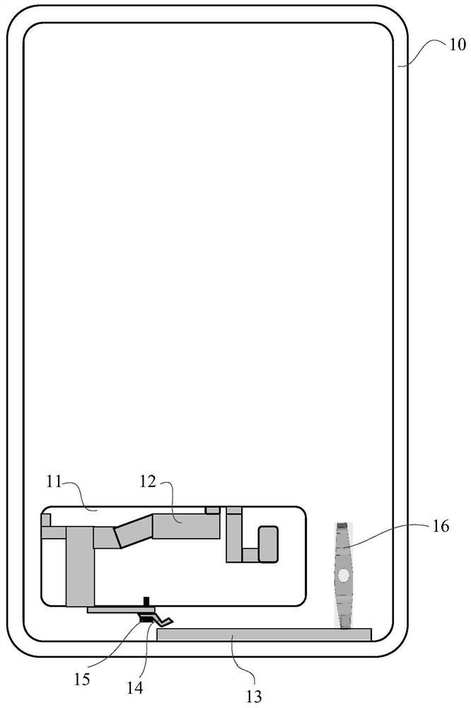
[0040] see figure 1 as shown, figure 1 A schematic diagram of the front structure of a mobile terminal antenna assembly provided by an embodiment of the present invention is shown, which includes:

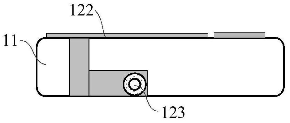
[0041] An antenna support 11, the antenna support 11 is built in the casing 10 of the mobile terminal;

[0042] The first antenna 12, the first antenna 12 is arranged on the antenna bracket 11;

[0043] The second antenna 13, the second antenna...

Embodiment 2

[0062] see Figure 5 as shown, Figure 5 A schematic diagram of the front structure of a mobile terminal 100 provided by an embodiment of the present invention is shown, and the mobile terminal includes the mobile terminal antenna assembly as described in the first embodiment above.

[0063] Wherein, for the setting of the antenna assembly of the mobile terminal in the mobile terminal 100, reference may be made to the description in the first embodiment.

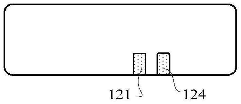
[0064] As an example, the mobile terminal 100 may also include: a small board 20, see Image 6 as shown, Image 6 Shows the schematic diagram of the front structure of the small plate 20 provided by the embodiment of the present invention, the small plate 20 is provided with a feed point 201, a feed point 202 and a small plate point 203, the feed point 201 and the antenna feed point of the mobile terminal antenna assembly 121 connection, the feed point 202 is connected to the antenna point 124 of the mobile terminal anten...


PUM


Abstract

The invention discloses a mobile terminal antenna assembly and a mobile terminal. The mobile terminal antenna assembly comprises a first antenna arranged on an antenna support and a second antenna arranged on an inner frame at one side of the bottom of a mobile terminal shell, and is provided with a first elastic sheet. The first end of the first elastic sheet is connected with the first antenna,and the second end of the first elastic sheet is connected with the second antenna. According to the mobile terminal antenna assembly, the utilization height is increased by using the first antenna arranged between the antennas, and the first antenna and the second antenna are connected by using the first elastic sheet, so that the utilization area and space of the mobile terminal antenna assemblyare effectively increased, and the performance of the mobile terminal antenna assembly is improved.

Description

technical field [0001] The present invention relates to the technical field of antennas, in particular to a mobile terminal antenna assembly and a mobile terminal. Background technique [0002] With the development of smartphones entering the 5G era, the design of mobile phones is becoming more and more complex and the thickness of mobile phones is getting thinner and thinner. This makes the area and space of built-in antennas in mobile phones smaller and smaller, and the design of built-in antennas is also facing greater challenges. challenge. [0003] Nowadays, the built-in antenna of the mobile phone is usually arranged on the antenna bracket inside the mobile phone casing or on the inner surface of the mobile phone casing. The effective space and area of ​​the antenna are limited, which is not conducive to improving the performance of the antenna. Contents of the invention [0004] The technical problem to be solved by the present invention is: how to effectively impr...

Claims


Application Information

Patent Timeline
Patent Type & Authority Applications(China)
IPC IPC(8): H01Q1/36H01Q1/24
CPCH01Q1/243H01Q1/36
Inventor 李稳廷
Owner GREE ELECTRIC APPLIANCES INC
Why Eureka
Try Eureka