
Epicondylitis clasp

A brace and epicondyle technology, applied in medical science, finger bandages, etc., can solve the problems of shaft damage, deflection, high load, etc., and achieve the effect of ensuring reliability

Active Publication Date: 2012-07-18
BAUERFEIND GMBH & CO
View PDF1 Cites 0 Cited by
  • Summary
  • Abstract
  • Description
  • Claims
  • Application Information

AI Technical Summary

Problems solved by technology

[0003] The aforementioned epicondylar brace must exert a higher pressure at the relevant position of the arm by means of its pressure pad, wherein the desired therapeutic effect occurs when the brace is placed and the retaining strap is folded under the pressure pad. A driving force is obtained on the shaft, which places a large load on the shaft, causing damage to the shaft
It has also been found that in some cases the brace can be placed too high or too low on the arm or deflected during placement and must be moved again by the user in order to place the brace with its If the pressure pad moves to the correct position, it will also generate a high load on the shaft of the pressure pad

Method used


Image

  • Epicondylitis clasp
  • Epicondylitis clasp
  • Epicondylitis clasp

Examples


Embodiment Construction

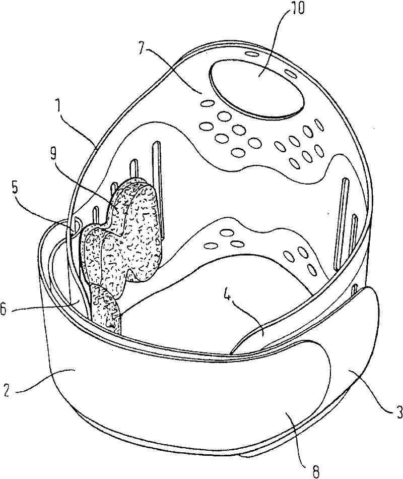
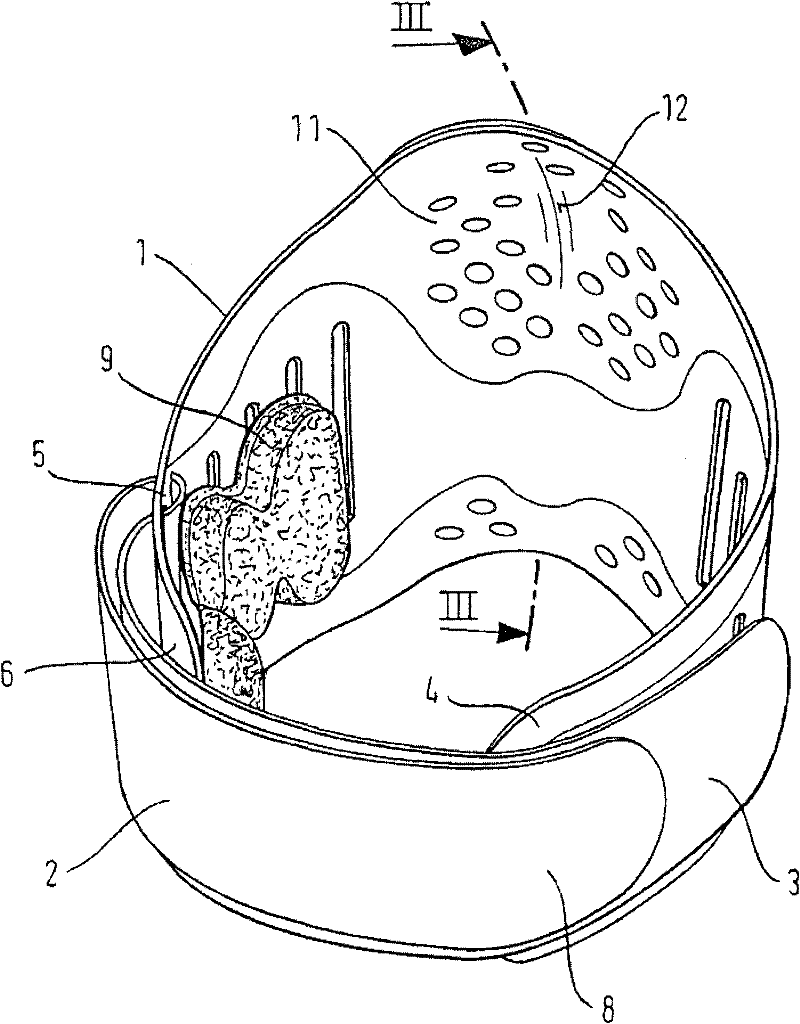
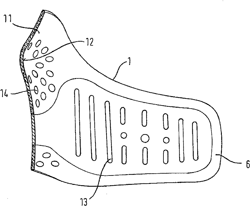
[0017] exist figure 1 The epicondylar brace shown in includes a retainer 1 which, when attached to the arm (see Figure 4 ) partially wraps around the arm when up. Here, the holding part 1 can leave an intermediate space between its ends 4 and 6 , which is bridged by a holding strip 2 . The retaining strap 2 is passed through an elongated grommet 5 (see also Figure 5 ) is wound on one end 6 of the retainer 1, and the outer part abuts against the other end 3 of the retaining band through its one lead-out end 8, and is fixed on the lead-out end 3 by Velcro fasteners. serve. The outlet 3 is likewise fastened to the end 4 of the holder 1 by means of Velcro fasteners. This connection of end 4 and outlet 3 can also be realized in another way. For example by snapping into pins in each mutually staggered hole (see for example Figure 6 ). By correspondingly tightening the retaining strap 2, the retainer 1 can be tensioned securely around the arm. This tension of the retaining...


PUM


Abstract

The invention relates to an epicondylitis clasp, wherein the holding part thereof, encompassing the arm, is tightenable by means of a steplessly adjustable securing strap, the inside of said epicondylitis clasp being provided with a pad for exerting pressure on a pressure-requiring area, said pad being in the form of an oblong pad attached to the holding part. A side of the holding part opposite the opening therein-said opening being bridgeable by the securing strap-is provided with a tab, wherein, with the holding part fitted on the arm, said tab covers the elbow joint and, by receiving the elbow, so encompasses the elbow joint that, when the holding part is fitted, the tab, which is guided by the elbow, serves as a positioning aid for positioning the holding part. The holding part can be fitted by means of the positioning aid to either the left or right arm and, for fitting to the left or right arm, is provided on its inside with a support for the pad, by means of which support the pad is removably attached to the holding part by securing means such that the holding part can be fitted on either the left or right arm with the pad in the therapeutically required position.

Description

technical field [0001] The invention relates to an epicondylar brace (Epikondylitisspange), the retainer of which can be fastened around the arm by means of infinitely adjustable retaining straps, and the epicondylar brace is provided on the inner side for applying pressure on the side where the pressure is required There is a pressure pad at the location, which is fastened to the holder as an elongated pad. Background technique [0002] Such a brace is described and shown in DE 197 16 705 C1. The location requiring pressure may be the epicondyle, which is the relevant (diseased) location for so-called tennis elbow. Furthermore, with the so-called golfer's elbow there is also a requirement to exert pressure on a region of the arm opposite the epicondyle. This is an example for some applications of therapeutically required positions, which are determined in individual cases by the treating physician. In order to design the brace to be used for both the right arm and the le...

Claims


Application Information

Patent Timeline
Patent Type & Authority Patents(China)
IPC IPC(8): A61F5/01A61F5/32
CPCA61F13/101A61F13/108A61F13/107A61F13/102
Inventor R·贝茨G·斯蒂尔
Owner BAUERFEIND GMBH & CO
Learn More