Supercharge Your Innovation With Domain-Expert AI Agents!

Sensor circuit

A technology of sensor circuit and sensor element, which is applied in the direction of instruments, adjusting electric variables, measuring devices, etc., and can solve the problem of circuit scale becoming larger

Inactive Publication Date: 2013-09-11
SII SEMICONDUCTOR CORP
View PDF1 Cites 0 Cited by
  • Summary
  • Abstract
  • Description
  • Claims
  • Application Information

AI Technical Summary

Problems solved by technology

[0007] However, the bandgap reference voltage generation circuit 11 and various current sources are required for temperature compensation, resulting in an increase in circuit scale.

Method used


Image

  • Sensor circuit
  • Sensor circuit
  • Sensor circuit

Examples


Embodiment Construction

[0021] Hereinafter, embodiments of the present invention will be described with reference to the drawings.

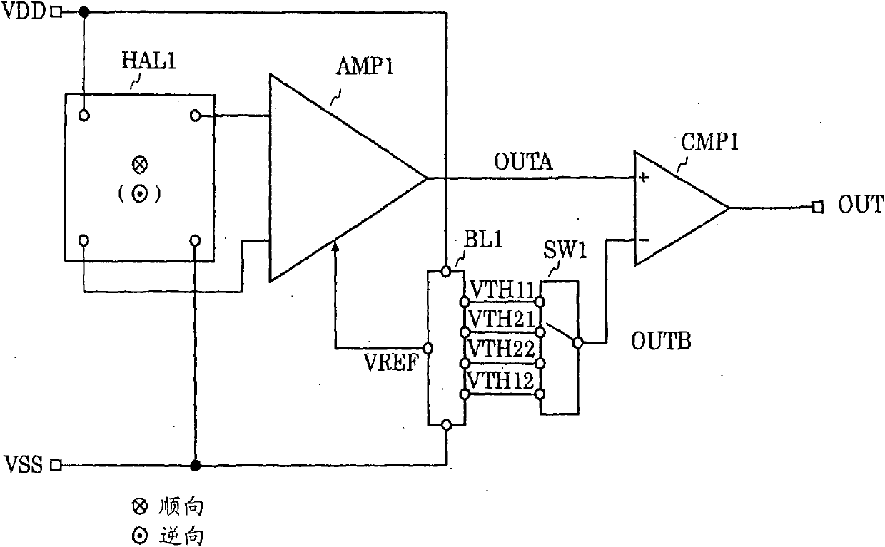
[0022] First, the configuration of the sensor circuit will be described. figure 1 is a diagram showing a sensor circuit.

[0023] The sensor circuit has a Hall element HAL1, an amplifier circuit AMP1, a comparison circuit CMP1, a reference voltage circuit BL1, and a switch circuit SW1.

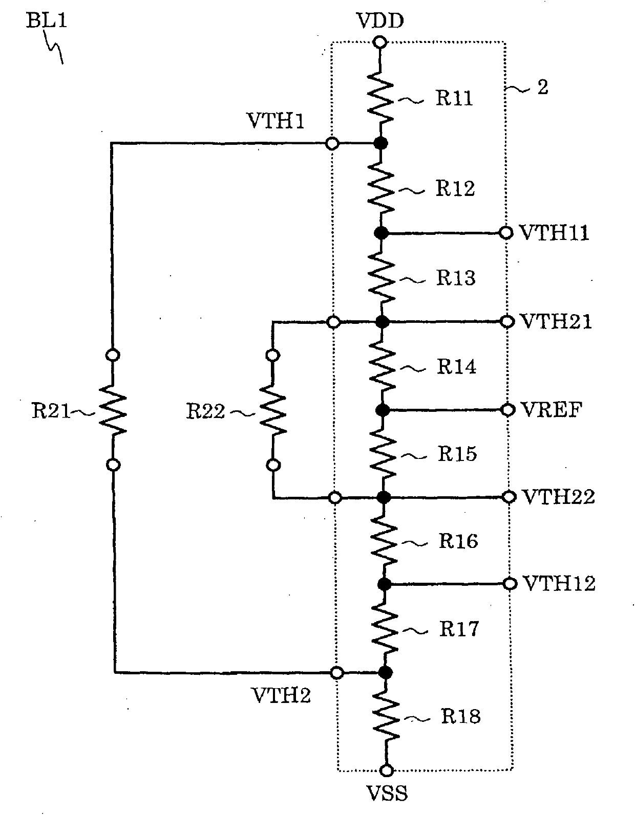
[0024] The first terminal of the Hall element HAL1 is connected to the power supply terminal, the second terminal is connected to the ground terminal, the third terminal is connected to the first input terminal of the amplifier circuit AMP1 , and the fourth terminal is connected to the second input terminal of the amplifier circuit AMP1 . The reference voltage terminal of the amplifier circuit AMP1 is connected to the reference voltage terminal of the reference voltage circuit BL1, and the output terminal is connected to the non-inverting input terminal of the comparison circuit CMP1....


PUM


Abstract

Provided is a sensor circuit that is small in circuit scale, but is capable of temperature compensation. A reference voltage circuit (BL1) which compensates a temperature includes only a voltage divider circuit, and hence the sensor circuit is small in circuit scale. The sensor circuit is also capable of temperature compensation because temperature changes of reference voltages (VTH11 and VTH12) and reference voltages (VTH21 and VTH22) match a temperature change of an output signal (OUTA) of an amplifier circuit (AMP1) which is caused by a temperature change of an output signal of a Hall element (HAL1).

Description

technical field [0001] The present invention relates to sensor circuits. Background technique [0002] Currently, electronic devices are mounted with various sensor circuits. For example, electronic equipment is equipped with a magnetic sensor circuit that detects the magnetic field of a magnet. The electronic device has a mechanism for folding a part of the main body. The folding mechanism has a magnet and a magnetic sensor circuit. When the folding mechanism is unfolded and closed, the distance between the magnet and the magnetic sensor circuit changes. The magnitude of the magnetic field generated by the magnet applied to the sensor circuit Change, when the magnetic field is above the specified value, the folding mechanism is in the unfolded state, and when it is smaller than the specified value, it is in the closed state. [0003] Here, generally, the output signal of the sensor circuit has a temperature coefficient. Therefore, the sensor circuit may be equipped with ...

Claims


Application Information

Patent Timeline
Patent Type & Authority Patents(China)
IPC IPC(8): G01R33/07H10N10/00
CPCG01R33/07G01R33/0029G05F1/567
Inventor 有山稔
Owner SII SEMICONDUCTOR CORP
Features
  • R&D
  • Intellectual Property
  • Life Sciences
  • Materials
  • Tech Scout
  • Unparalleled Data Quality
  • Higher Quality Content
  • 60% Fewer Hallucinations
Learn More