
Battery fixing device

A battery cover and locking technology, which is applied to battery pack components, circuits, electrical components, etc., can solve problems such as inconvenience in use and difficulty in disassembling and assembling the battery cover.

Inactive Publication Date: 2010-06-16
SHENZHEN FUTAIHONG PRECISION IND CO LTD
View PDF0 Cites 2 Cited by
  • Summary
  • Abstract
  • Description
  • Claims
  • Application Information

AI Technical Summary

Problems solved by technology

[0004] Although this type of battery cover locking structure can firmly fix the battery in the housing, once the battery cover is combined with the housing, the battery cover is difficult to disassemble, causing inconvenience in use

Method used


Image

  • Battery fixing device
  • Battery fixing device
  • Battery fixing device

Examples


Embodiment Construction

[0014] The invention discloses a locking structure of a battery cover, which is suitable for portable electronic devices such as mobile phones.

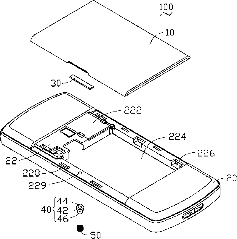
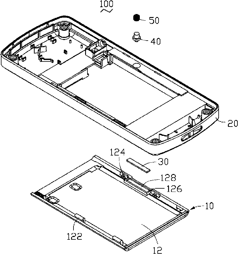
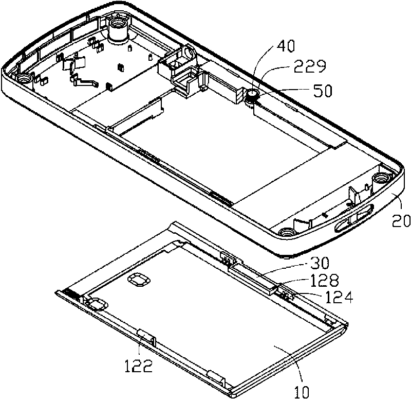
[0015] see figure 1 , the battery cover locking structure 100 includes a battery cover 10, a housing 20, a magnetic element 30 provided on the battery cover 10, an iron core 40 provided on the housing 20, and an iron core 40 provided on the iron core Coil 50 on 40. ginseng Image 6 , the battery cover 10 and the casing 20 are locked together by the attractive force between the magnetic element 30 and the iron core 40 . The coil 50 is electrically connected to an internal circuit (not shown) of the battery cover locking structure 100 . When the coil 50 is energized, the coil 50 generates a magnetic field opposite to the magnetic pole of the magnetic element 30 , thereby generating a repulsive force between the iron core 40 and the magnetic element 30 . In this way, the engagement between the battery cover 10 and the casing 20 is r...


PUM


Abstract

The invention provides a battery cover blocking structure which comprises a shell and a battery cover blocked on the shell, wherein a plurality of blocking parts are arranged at one side of the battery cover, and a groove is formed at the other side of the battery cover; the shell is provided with a plurality of blocking grooves corresponding to the blocking parts, the blocking parts are accommodated in the blocking grooves, and the shell is provided with a through hole corresponding to the groove; the battery cover blocking structure also comprises an magnetic element and an iron core, wherein the magnetic element is accommodated in the groove and combined with the battery cover into a whole, the iron core is accommodated in the through hole and combined with the shell into a whole, and the magnetic element and the iron core are magnetically combined together.

Description

technical field [0001] The invention relates to a locking structure of a battery cover, in particular to a locking structure of a battery cover applied to portable electronic devices such as mobile phones. Background technique [0002] Mobile phones and personal digital assistants (Personal Digital Assistant, PDA) and other portable electronic devices are increasingly widely used, and the batteries that provide energy for portable electronic devices have to be replaced due to energy consumption. In order to make the battery easy to install, people have designed Many battery cover snap-lock structures. [0003] The existing locking structure of the battery cover of the portable electronic device generally includes a groove opened on the casing of the portable electronic device and a battery cover capable of covering the groove. After the battery is installed in the groove, the battery cover is fastened on the casing to limit the battery in the groove. In order to fix the ba...

Claims


Application Information

Patent Timeline
Patent Type & Authority Applications(China)
IPC IPC(8): H01M2/10H01M50/247H01M50/264H01M50/289
CPCY02E60/12H04M1/0262H01M2/1066Y02E60/10
Inventor 伍席球张光祥
Owner SHENZHEN FUTAIHONG PRECISION IND CO LTD
Learn More