Light source driving device

A light source driving and light source module technology, which is applied to light sources, electric light sources, lighting devices, etc., can solve the problems of device component damage, high voltage, and increased device cost.

Inactive Publication Date: 2010-06-23
GRENERGY OPTO INC
View PDF4 Cites 0 Cited by
  • Summary
  • Abstract
  • Description
  • Claims
  • Application Information

AI Technical Summary

Problems solved by technology

However, the input voltage Vi will cause the inductor L or the transformer to act due to the voltage input process, which will cause high voltage generation. If the device is not to be damaged, it is necessary to use a contro

Method used


Image

  • Light source driving device
  • Light source driving device
  • Light source driving device

Examples


Embodiment Construction

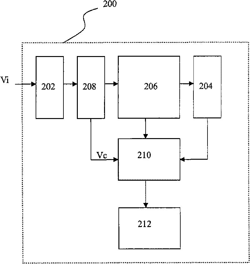
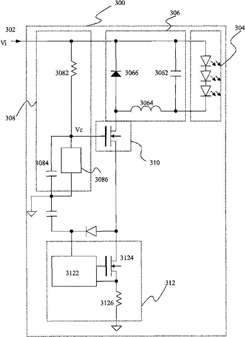
[0029] The invention discloses a light source driving device, which makes use of at least one switch and / or control module to determine whether to drive the light source, and uses a conversion module to drive multiple light sources, and provides a surge voltage protection device to avoid damage to the control module, so that the surge voltage Only related to external components. In order to make the narration of the present invention more detailed and complete, refer to the following description and cooperate figure 2 and image 3 schema.

[0030] refer to figure 2 , is a block diagram of the light source driving device of the present invention. In this embodiment, a light source driving device 200 is provided, including a voltage input terminal 202 , a light source module 204 , a conversion module 206 , a voltage stabilization module 208 , a first switch 210 and a control module 212 . The voltage input terminal 202 receives the input voltage Vi, for example, the input v...


PUM


Abstract

The invention provides a light source driving device. The light source driving device comprises a voltage input end, a light source module, a conversion module, a voltage stabilization module, a first switch and a control module, wherein the voltage input end receives an input voltage; the light source module comprises a plurality of light emitting units; the conversion module is electrically connected with the plurality of light emitting units; the voltage stabilization module is connected with the voltage input end and provides a stable output voltage; the first switch is electrically connected with the conversion module and the voltage stabilization module, receives the stable output voltage, and is used for determining whether the first switch is on; the control module is electrically connected with the first switch; and the control module and the first switch are controlled, so that the input voltage can drive the light source module.

Description

technical field [0001] The invention relates to a light source driving device, in particular, at least one switch and a control module are used to determine whether to drive the light source. Background technique [0002] Known technology, can refer to figure 1 In the present invention, a controller is used together with an electronic switch Q as a control circuit for controlling the light-emitting diode LED; in this circuit, the control unit controls the opening or closing of the electronic switch Q to realize the opening of the light-emitting diode LED. However, the input voltage Vi will cause the inductor L or the transformer to act due to the voltage input process, which will cause high voltage generation. If the device is not to be damaged, a control unit with high withstand voltage characteristics must be used. However, the control unit with high withstand voltage will increase the cost of the device, and if not used, it may cause damage to the components of the devic...

Claims


Application Information

Patent Timeline
IPC IPC(8): H05B37/02
Inventor 王燕晖洪家杰吴继浩
Owner GRENERGY OPTO INC
Why Eureka
Try Eureka